6. Description of Parameters
- 195 -
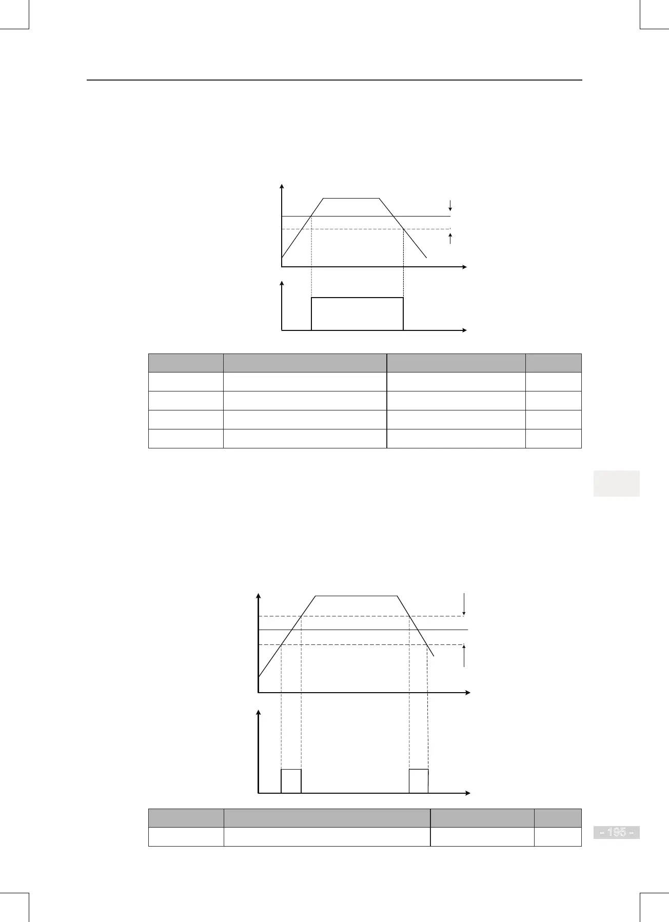
6.11.3 Frequency Detection (FDT)
This function sets detection values of output frequency and sets hysteresis level for the
frequency detection function.
Figure 6-63 Frequency detection
Time (t)
Output
frequency (Hz)
Frequency
detection level 1
Time (t)
ON
Frequency
hysteresis
= F8-19 x F8-20
(
DO, relay)
Function Code Parameter Name Setting Range Default
F8-19
Frequency detection value 1 0.00 Hz to max. frequency 50.00 Hz
F8-20
Frequency detection hysteresis 1 0.0% to 100.0% 5.0%
F8-28
Frequency detection value 2 0.00 Hz to max. frequency 50.00 Hz
F8-29
Frequency detection hysteresis 2 0.0% to 100.0% 5.0%
F8-19: It sets detection value for digital output function 3. When running frequency exceeds the
detection value, digital output terminal set for function 3 becomes on.
F8-20: It sets hysteresis level for the frequency detection function. It is a percentage of the
frequency detection value (F8-19).
6.11.4 Frequency Reference Reached Detection Width
This function sets the detection width of the frequency reference.
Figure 6-64 Frequency reached detection width
Detection width =
max. frequency x F8-21
Time
(t)
Output
frequency (Hz)
Frequency reference
ON ON
Frequency
reached signal
Function Code Parameter Name Setting Range Default
F8-21
Detection width of target frequency reached 0.0% to 100.0%% 0.0%
 Loading...
