Goodrive300 Series VFD Basic operation instruction
125
Chapter 7 Basic operation instruction
7.1 What this chapter contains
This chapter describes the internal function modules of the VFD in details.
• Ensure that all terminals are connected properly and tightly.
• Ensure that the power of the motor corresponds to that of the VFD.
7.2 First powering on
Check before powering on
Please check according to the installation list in chapter two.
First powering operation
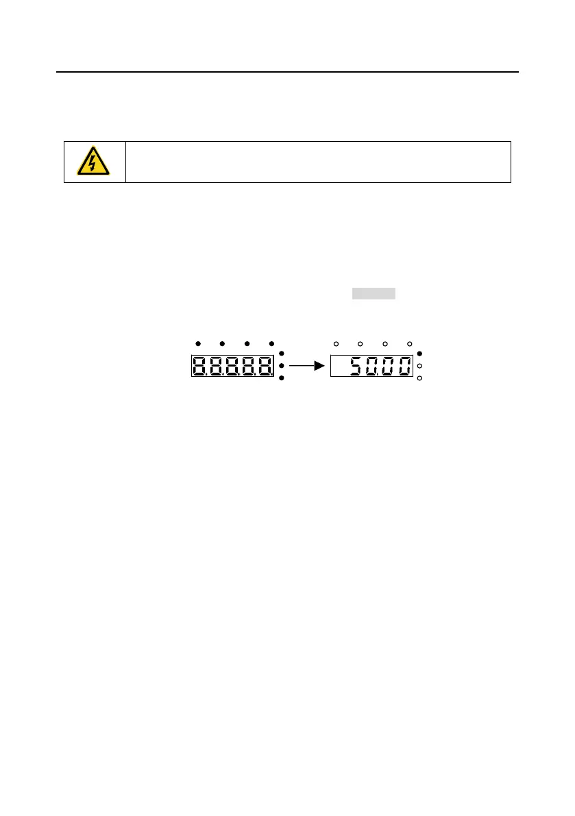
Check to ensure there is no mistake in wiring and power supply, switch on the air switch of the AC
power supply on the input side of the VFD to power on the VFD. 8.8.8.8.8. will be displayed on the
keypad, and the contactor closes normally. When the character on the nixie tubs changes to the set
frequency, the VFD has finished the initialization and it is in the stand-by state.
"88888" is displayed and all the
seven indicators are on.
Standby state
Below diagram shows the first operation: (take motor 1 as the example)
 Loading...


