EasyManua.ls Logo

INVT Goodrive300 Series User Manual

INVT Goodrive300 Series
289 pages
To Next Page IconTo Next Page
To Previous Page IconTo Previous Page
Page #218 background imageLoading...
Page #218 background image
Goodrive300 Series VFD Communication protocol
213
else crc_value=crc_value>>1;
} }
return(crc_value);
}
In ladder logic, CKSM calculated the CRC value according to the frame with the table inquiry. The
method is advanced with easy program and quick calculation speed. But the ROM space the program
occupied is huge. So use it with caution according to the program required space.
10.4 RTU command code and communication data illustration
10.4.1 Command code: 03H
03H (correspond to binary 0000 0011), read N words (Word)(Max. continuous reading is 16
words)
Command code 03H means that if the master read data form the VFD, the reading number depends
on the "data number" in the command code. The Max. continuous reading number is 16 and the
parameter address should be continuous. The byte length of every data is 2 (one word). The following
command format is illustrated by hex (a number with "H" means hex) and one hex occupies one byte.
The command code is used to read the working stage of the VFD.
For example, read continuous 2 data content from0004H from the VFD with the address of 01H (read
the content of data address of 0004H and 0005H), the frame structure is as below:
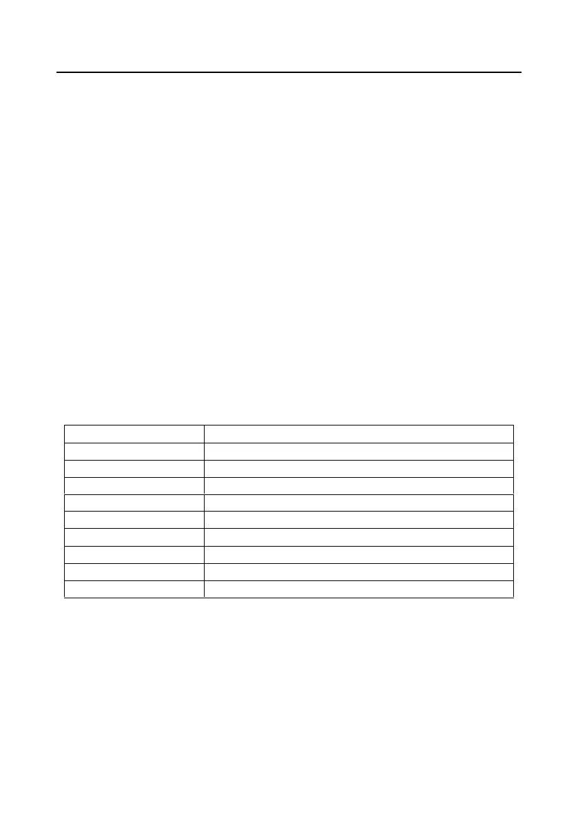
RTU master command message (from the master to the VFD)
START
T1-T2-T3-T4 (transmission time of 3.5 bytes)
ADDR
01H
CMD
03H
High bit of the start bit
00H
Low bit of the start bit
04H
High bit of data number
00H
Low bit of data number
02H
Low bit of CRC
85H
High bit of CRC
CAH
END
T1-T2-T3-T4 (transmission time of 3.5 bytes)
T1-T2-T3-T4 between START and END is to provide at least the time of 3.5 bytes as the leisure time
and distinguish two messages for the avoidance of taking two messages as one message.
ADDR = 01H means the command message is sent to the VFD with the address of 01H and ADDR
occupies one byte
CMD=03H means the command message is sent to read data form the VFD and CMD occupies one
byte
"Start address" means reading data form the address and it occupies 2 bytes with the fact that the

Table of Contents

Question and Answer IconNeed help?

Do you have a question about the INVT Goodrive300 Series and is the answer not in the manual?

INVT Goodrive300 Series Specifications

General IconGeneral
BrandINVT
ModelGoodrive300 Series
CategoryDC Drives
LanguageEnglish

Summary

Chapter 1 Safety precautions

Safety definition

Defines terms like Danger, Warning, and Note for safety instructions.

Warning symbols

Describes standard symbols used in the manual for warnings and cautions.

Safety guide

Provides essential guidelines and precautions for safe operation and handling.

Chapter 2 Quick start-up

Unpacking inspection

Checks to perform after receiving the VFD to ensure it is undamaged and complete.

Application confirmation

Verifies the VFD is suitable for the intended load and supply voltage before use.

Environment

Specifies conditions for installation site, temperature, humidity, and altitude.

Basic commissioning

Outlines the fundamental steps for initial setup and operation of the VFD.

Chapter 3 Product overview

Basic principles

Explains the fundamental operation and circuit diagram of the VFD.

Product specification

Details electrical and technical specifications for different VFD models.

Name plate

Describes the information found on the VFD's nameplate for identification.

Model code

Explains how to interpret the VFD's model code for product identification.

Rated specifications

Provides detailed electrical ratings for various models, including power, current, and voltage.

Structure diagram

Illustrates the physical structure and components of the VFD.

Chapter 4 Installation guide

Mechanical installation

Covers environmental requirements and physical installation directives for the VFD.

Standard wiring

Details main circuit and control circuit wiring diagrams and terminal connections.

Layout protection

Explains protection measures for the VFD and cables against short circuits and overload.

Chapter 5 Keypad operation procedure

Keypad

Describes the VFD keypad's components and functions for control and parameter adjustment.

Keypad displaying

Explains the different display states and information shown on the keypad.

Keypad operation

Details how to navigate menus and modify function codes using the keypad.

Chapter 6 Function parameters

Goodrive300 general series function parameters

Lists and describes all function parameters, grouped by function codes (P00-P29).

Chapter 7 Basic operation instruction

First powering on

Step-by-step guide for powering on the VFD for the first time after installation.

Vector control

Explains the principles and application of vector control for motor operation.

SVPWM control

Details the SVPWM control mode and its benefits for specific load types.

Chapter 8 Fault tracking

Fault instruction and solution

Provides guidance on identifying faults and troubleshooting resolutions for VFD errors.

Common fault analysis

Flowcharts for diagnosing common VFD issues like motor not working or vibration.

Chapter 9 Maintenance and hardware fault diagnostics

Maintenance intervals

Lists recommended routine checks and intervals for VFD maintenance.

Cooling fan

Details maintenance and replacement procedures for the VFD's cooling fan.

Capacitors reforming

Explains the procedure for reforming DC bus capacitors if the VFD was stored long-term.

Chapter 10 Communication protocol

Brief introduction of Modbus protocol

Provides an overview of the Modbus protocol and its application in VFDs.

RS485

Details the RS485 interface characteristics, baud rates, and transmission distances.

RTU communication frame format

Explains the structure and error checking methods for RTU communication frames.

Appendix A Extension card

PROFIBUS extension card

Describes the PROFIBUS standard and its application with VFDs.

EC-TX-103 communication card

Details the EC-TX-103 communication card, its functions, and appearance.

System configuration

Explains how to configure the master station and VFD for PROFIBUS communication.

Appendix B Technical data

Ratings

Covers VFD capacity, power ratings, and applicable ambient temperatures.

Derating

Explains load capacity reduction due to temperature, altitude, and carrier frequency.

Grid specifications

Details grid voltage, short-circuit capacity, and frequency specifications.

Motor connection data

Provides specifications for connecting asynchronous and synchronous motors.

Appendix C Dimension drawings

Keypad structure

Shows the structure and installation details of the VFD keypad.

VFD structure

Illustrates the internal components and overall structure of the VFD.

Dimensions for VFDs of AC 3PH 380V(-15%)–440V(+10%)

Provides dimensional drawings and installation data for 380V/440V VFDs.

Appendix D Peripheral options and parts

Peripherial wiring

Illustrates the external wiring diagrams for VFDs and their accessories.

Power cables

Details specifications and recommendations for power and motor cable selection.

Control cables

Provides guidelines for selecting and wiring analog and digital control cables.

Breaker and electromagnetic contactor

Explains the selection and configuration of circuit breakers and contactors for VFD protection.

Braking system

Covers the selection and installation of braking components like resistors and units.

Appendix E Further information

Product and service queries

Information on how to contact INVT for product support and service.

Documents on the Internet

Guidance on accessing VFD manuals and product documents online.

Related product manuals