Goodrive300 Series VFD Keypad operation procedure
34
Chapter 5 Keypad operation procedure
5.1 What this chapter contains
This chapter describes the keys, indicators, and display of the keypad, and how to view and modify
function code settings through the keypad.
5.2 Keypad
The keypad is used to control Goodrive300 series VFDs, read the state data and adjust parameters. If
you need to use the keypad in another place rather than on the VFD, use a network cable with a
standard RJ45 crystal head as the extension cable.
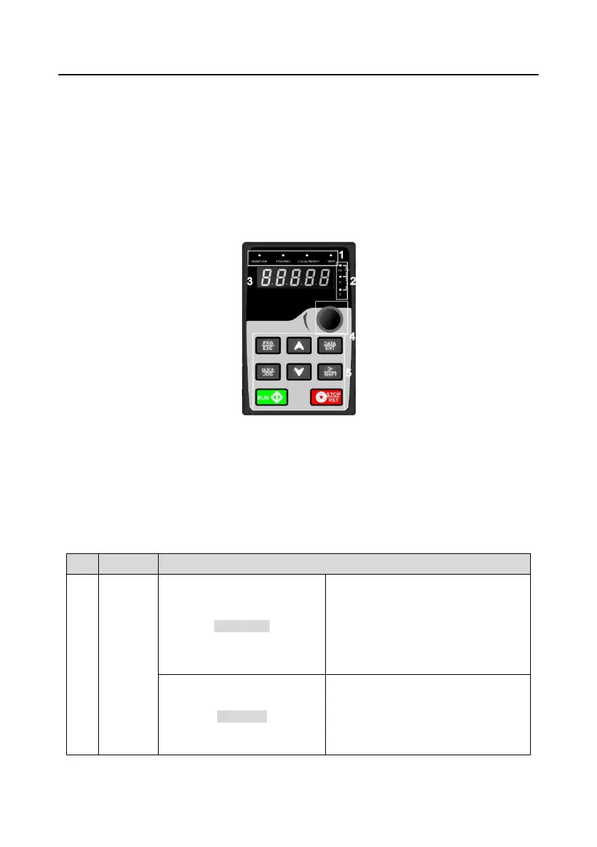
Figure 5-1 Keypad
Note:
1. The LED keypad is standard but the LCD keypad which can support various languages,
parameters copy and 10-line displaying is optional.
2. It is necessary to use M3 screw or installation bracket to fix the external keypad. The installation
bracket for VFDs of 380V 1.5–30kW and 500V 4–18.5kW is optional but it is standard for the VFDs of
380V 37–500kW, 500V 22–75kW and 660V.
LED off means that the VFD is in the
stopping state; LED blinking means the
VFD is in the parameter autotune state;
LED on means the VFD is in the running
state.
FED/REV LED
LED off means the VFD is in the forward
rotation state; LED on means the VFD is
in the reverse rotation state
 Loading...


