Goodrive300 Series VFD Basic operation instruction
156
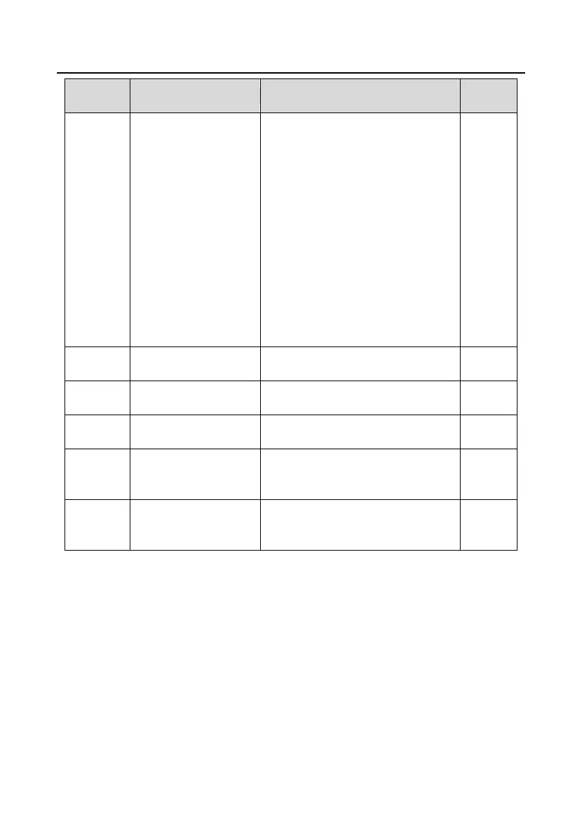
Detailed instruction of parameters
0: UP/DOWN terminals setting valid
1: UP/DOWN terminals setting valid
LED tens: frequency control selection
0: Only valid when P00.06=0 or
P00.07=0
1: All frequency means are valid
2: When the multi-step are priority, it is
invalid to the multi-step
LED hundreds: action selection when
stop
0: Setting valid
1: Valid in the running, clear after stop
2: Valid in the running, clear after
receiving the stop commands
UP terminals frequency
changing ratio
DOWN terminals
frequency changing ratio
Display current set frequency of the VFD
Range: 0.00Hz–P00.03
Display current ramp given frequency of
the VFD.
Range: 0.00Hz–P00.03
Display the adjustment through the
keypad of the VFD.
Range: 0.00Hz–P00.03
7.9 Analog input
Goodrive300 series VFDs have three analog input terminals and 1 high-speed pulse input terminals
(of which, AI1 and AI2 are 0–10V/0–20mA and Al can select voltage input or current input by J3, AI2
can select voltage input or current input by J4 and AI3 is for -10–10V) as the standard configuration.
The inputs can be filtered and the maximum and minimum values can be adjusted.
 Loading...


