Goodrive300 Series VFD Dimension drawings
251
Appendix C Dimension drawings
C.1 What this chapter contains
Dimension drawings of the Goodrive300 are shown below. The dimensions are given in millimeters
andinches.
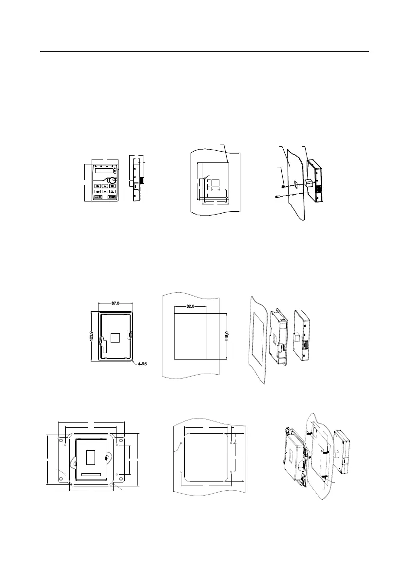
C.2 Keypad structure
C.2.1 Structure chart
Hol e-c utting size a nd diagr am fo r non-b racke t k eyp ad ins ta llati on
2-
?
4
Panel
2-M3 x10 combination screw
Outline o f the keypad
Keyp ad
3 7 . 1
1 0 9 . 3
8 . 6
1 0 9 . 3
58
56
2 0 . 419
3 4 . 4
7 1 . 3
6 . 7
19
7 1 . 3
18
C.2.2 Installaiton with bracket (optional)
Note: It is necessary to use M3 screw or installation bracket to fix the external keypad. The
installation bracket for VFDs of 380V 1.5–30kW and 500V 4–18.5kW is optional but it is standard for
the VFDs of 380V 37–500kW, 500V 22–500kW and 660V.
Keypad bracket
Customer installation demension
Installation with bracket for VFDs of 380V 1.5–315kW and 660 V 22–630kW (optional)
4-R12
106.0
160.0
125.0
145.5
81.0
135.5
4-Φ4.5
108.0
4-M4×15
(Self-clinching
stud)
8.5
28.4
81.0
137.5
125.0
125
8.5
28.4
108
137.5
81
4-M4×15
(Self-clinching
stud)
4-R13
Customer installation dimensions
Installation with bracket for VFDs of 380V 37–315kW and 660 V 22–630kW (standard)
 Loading...


