6A–68 ENGINE MECHANICAL
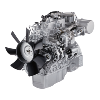
2. Use an inside dial indicator or an inside micrometer
to measure the idler gear inside diameter.
If the clearance between the idler gear shaft outside
diameter and the idler gear inside diameter exceeds
the limit, the idler gear and/or shaft must be
replaced.
Idler gear shaft and Idler gear clearance
Shaft A
Standard: 0.025 – 0.075 mm (0.00098 – 0.00295 in)
Limit: 0.2 mm (0.008 in)
Shaft B and C
Standard: 0.020 – 0.062 mm (0.0008 – 0.0024 in)
Limit: 0.2 mm (0.008 in)
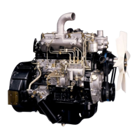
Installation
1. Install the idler gear B shaft.
1. Install the idler gear B shaft to the cylinder body.
The idler gear shaft oil port must be facing the
cylinder head.
2. Tighten the idler gear shaft bolts to the specified
torque.
Torque: 31 N·m (3.2 kgm/23 lbft)
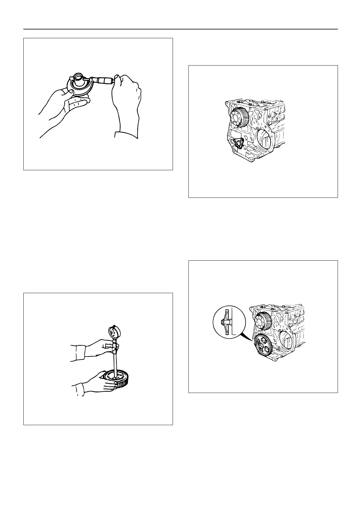
2. Install the idler gear B to the idle gear shaft.
1. Apply engine oil to the idler gear B inside and
thrust areas.
2. Install the idler gear to the idler gear shaft.
3. Tighten the idler gear bolts to the specified torque.
Torque: 95 N·m (9.7 kgm/70 lbft)
3. Install the oil pump to the cylinder block.
1. Carefully wipe any foreign material from the
cylinder body rear surface.
2. Apply engine oil to the cylinder body inside
bushing.
014EY00175
014EY00054
014EY00055
014EY00176
 Loading...