Figure 10
Figure 11
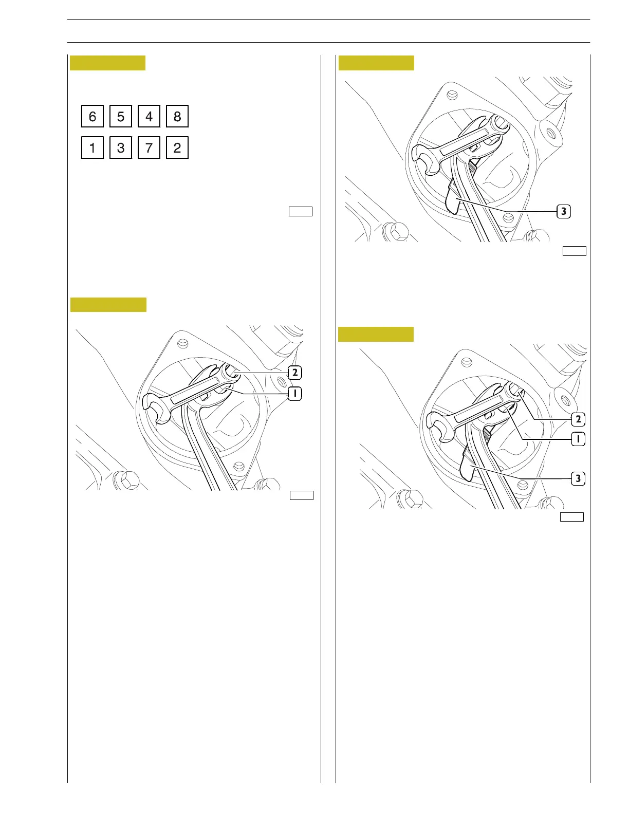
- Using the wrench kit 99368503, loosen the lo ck nut (1)
of the adjuster screw (2).
- Insert the tappet feeler gauge (0.50) 99368545 (3).
BALANCING
ADJUST
SECOND STEP
- To make the adjustment, proceed as illustrated here:
Figure 12
Figure 13
- With kit wrench 99368503, screw or unsc rew the
adjuster screw (2).
- Check that the tappet feeler gauge (3) can slide with a
slight amount of friction.
Keeping t he adjuster screw (2) still use wrench
99368503 to lock the check nut of the adjuster screw
(1).
81606
82184
82183
82185
SECTION 3 - INDUSTRIAL APPLICATION
89
VECTOR 8 ENGINES
Print P2D32V001E Base - April 2006
 Loading...
