Figure 14
- Adjust the other valves in the order shown on previous
page.
- Now close all 16 covers, extract the tool for turning the
flywheel and close the flywheel cover.
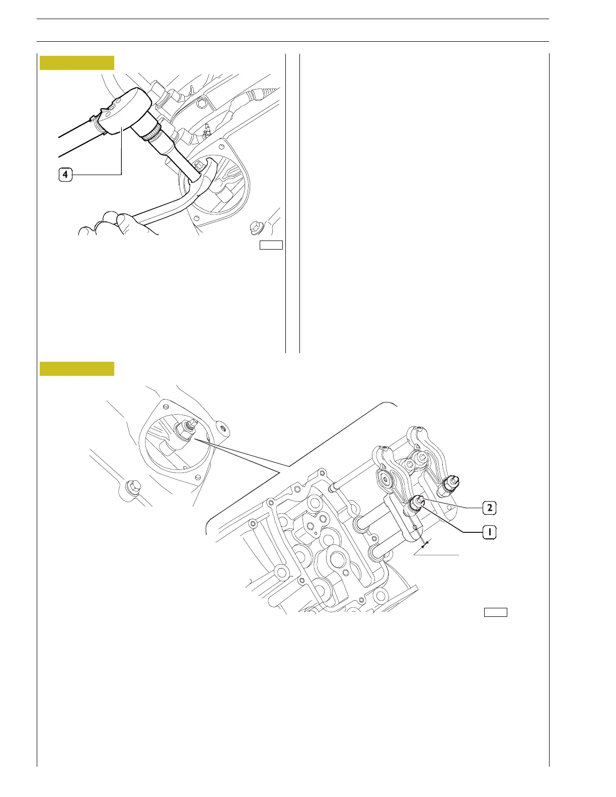
Tightening torque 7 ÷ 10 Nm.
Figure 15
1. Adjuster screw lock nut — 2. Adjuster screw.
- Apply the 10 — 60 Nm torque wrench with the 3/8”
square c onnection 99389831 (4) to the wrench
99368503 to lock th e lock nut to a torque of 40 Nm.
0,5 mm
0,5 mm
82186
81611
90
SECTION 3 - INDUSTRIAL APPLICATION
VECTOR 8 ENGINES
Base - April 2006 Print P2D32V001E
 Loading...
