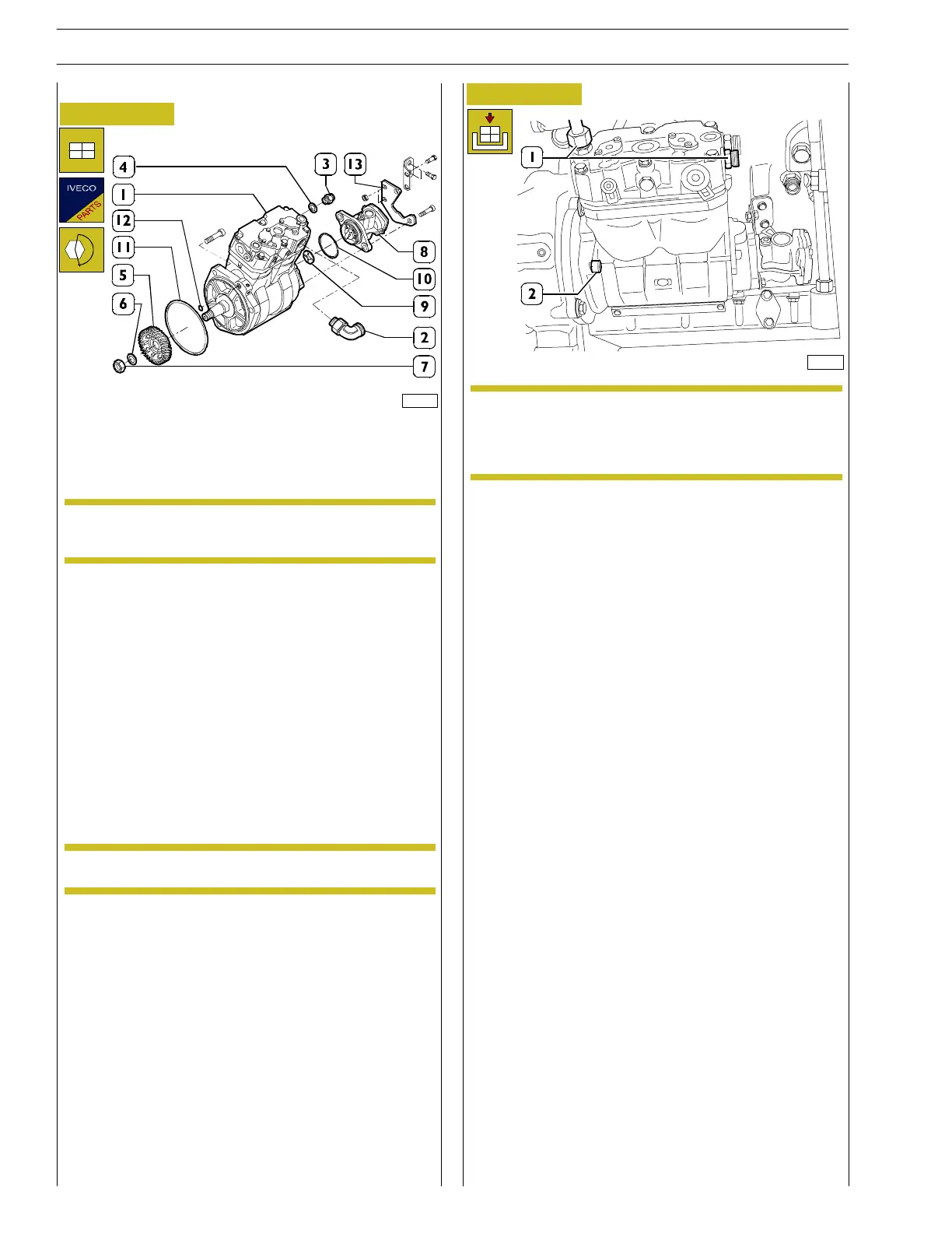
Figure 77
- On the bench, fit the previously removed fittings onto
the compressor (1): suction (2) and compression (3)
fittings: thread M26 = 100 Nm.
Change the gasket (4) at the fittin g mounted on the
compression port.
- Insert the gear (5), flat washer (6) and screw down the
nut (7), tightening to a torque of from 160 ÷ 180 Nm.
- Fit the low-pressure pump (8), inserting the universal
joint (9) and O-rin g (10).
Change the gaskets (10), (11) and (12).
Should compressor have been dismou nted join tly
with spacer, tigh ten (M12x1.75) screws securing it
to gears box at 42 ÷ 51 Nm tightening torque.
- Put compressor into its seat by tighten i ng (M12x1.75) at
74÷90NmNmtorque.
- Secure bracket (13, Figure 77) to engine bloc k.
- During assembly, check th at the coupling drive (9) an d
the teeth on the front of the secondary circuit cooling
pump gear show n o signs of wear or cracks. Change any
damaged parts.
- Fit support bracket (13) and tighten the s crews securing
the low—pressure pump support to the air compressor
to the prescribed to rque: 42÷51 Nm.
For DRAGON applications
89697
NOTE
NOTE
89698
Figure 78
NOTE
36
SECTION 3 - INDUSTRIAL APPLICATION
VECTOR 8 ENGINES
Base - April 2006 Print P2D32V001E
 Loading...
