31 - 8
Operation (cont’d)
Boom Spool Selection
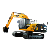
1. Neutral (Refer to Fig. 1, 5).
This valve has an anti-drift valve installed on boom 1 port.
Under neutral status, the poppet (12) is seated properly by
the pressure from port 4B3 which enters the spring chamber
(14) from the passage (15), the spool (13) and the passage
(16).
2. Up (2 speed confluence) (Refer to Fig. 1, 6).
When pilot port 4Pb3 is pressurised and the boom 1 spool is
selected (Fig 6), the 4-spool neutral passage (a) is closed
and the oil delivered from port 4P through the parallel
passage (b) and pushes up the load check valve (15). The
flow passes through passage (e) spool neck and pushes
open the anti-drift valve poppet (12) and flows into port 4B3.
When the boom 1 spool is selected, the boom 2 spool is
pressurised through the passage (13) the flow to the neutral
passage (A) is cut off. The oil delivered from port 5P flows
through passage (B), pushes open load check valve (16) and
flows through passage (E) through the spool neck and
passage (5), to port 4B3.
The return oil from cylinder port 4A3 flows from boom 1
spool neck and is released to the tank passage.
3. Lower (Refer to Fig. 1, 7).
When the pilot port 4Pa3 is pressurised and the boom 1
spool is selected (Fig. 7), the 4-spool neutral passage (a) is
cut off and the oil delivered from port 4P flows through the
4-spool parallel passage (b), pushes open the load check
valve (15) and flows through passage (e) from cylinder port
4A3.
When the boom 1 spool is selected, port PLc1 is
pressurised, the spool (13) of the anti-drift valve is switched.
The pressure in the spring chamber (14) is reduced and the
poppet (12) is opened, the return oil from port 4B3 flows
from the boom 1 spool neck to the tank.
Section E Hydraulics
9803/6020
Section E
31 - 8
Issue 1
Control Valve
289800
Fig. 5
A
B
C
E
D
A Boom 2
B Boom 1
C To Arm 2 Section
D To Service Section
E Neutral State
 Loading...