6 - 6
Testing
After dismantling and assembly of the traction
motor/reduction gear assembly, install on the machine (see
Removal and Replacement), but do not fit the track at this
stage. Carry out the ‘no load’ functional tests detailed below.
Preparation for Testing
Obtain the following test equipment:
Pressure gauge - 35 bar (500 lbf/in
2
, 35 kgf/cm
2
).
Receptacle for motor drain oil - 5 litre (1.1 gal) capacity.
Stopwatch.
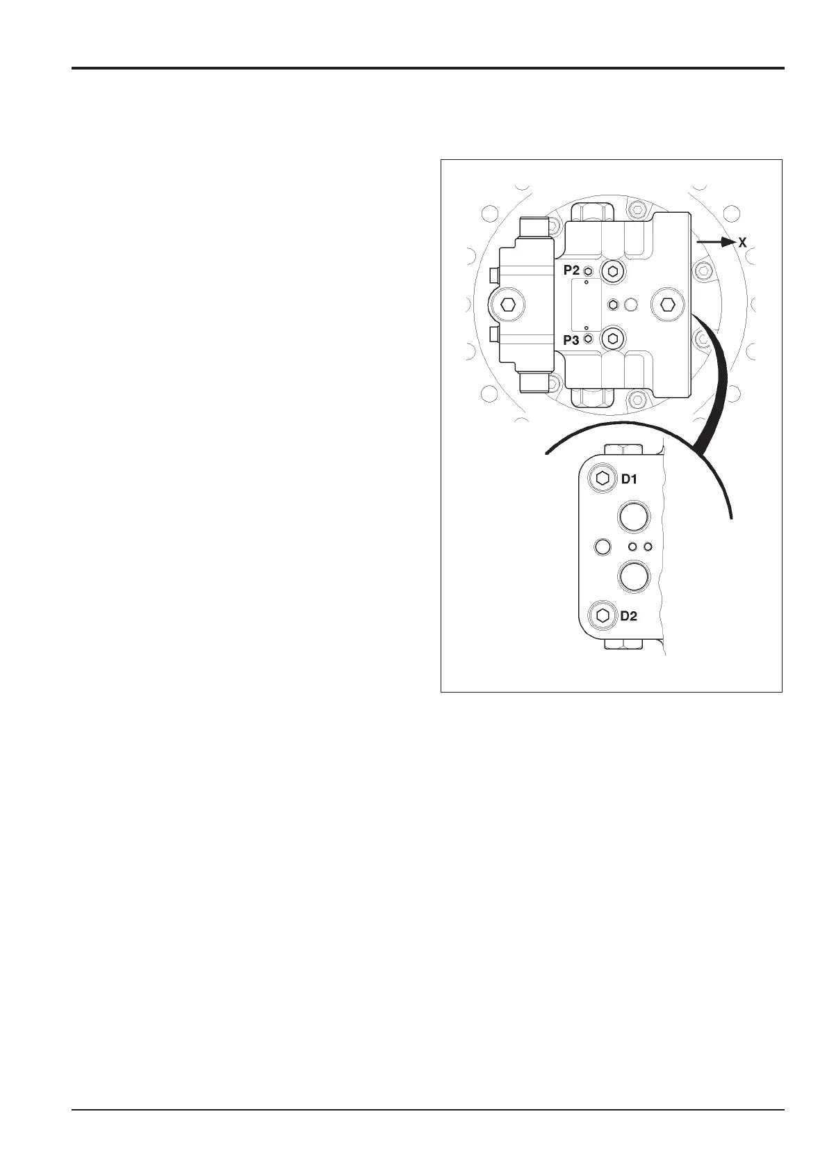
Connect the pressure gauge to test point P3 (left hand
motor) or P2 (right hand motor) on the inboard face of the
rear flange.
Run-in the traction motor by operating in both forward and
reverse directions at 10 rpm and 20 rpm for at least one
minute in each direction at each speed setting.
Functional Tests
1 Run the motor until the hydraulic oil temperature
reaches 45 - 55 °C (113 - 131 °F) and the reduction
gear hub external temperature reaches 40 - 80 °C (104
- 176 °F).
2 With the motor running at 10 rpm read the hydraulic
pressure, which should not be greater than 15.7 bar
(227.5 lbf/in
2
, 16 kgf/cm
2
).
3aStop the engine and operate the travel controls to
release system residual pressure. Disconnect the
hose from motor casing drain port D1 (left hand
motor) or D2 (right hand motor). In place of the hose
removed, connect an open ended hose long enough
to reach the oil receptacle.
b Start the engine and, using the travel control, run
the traction motor at 10 rpm for one minute and
then stop it. Measure the amount of drain oil
collected in the receptacle. This should not exceed
0.5 litres (0.11 U.K. gal).
Note: The drain oil quantities given are applicable to a new
motor. These will increase slightly as wear takes place.
4 If the above tests are satisfied, install the machine
track. If either of the tests fail, remove the
motor/reduction gear assembly from the machine.
Dismantle and thoroughly check the motor section for
further damage and/or wear and replace any suspect
parts. Repeat steps 1 to 4.
Note: The above illustration shows the inboard view of the
motor mounted on the left hand side of the machine, with X
indicating the front of the machine. To visualise the motor
mounted on the right hand side of the machine, rotate each
image through 180° so that P3 is above P2 and D2 is above
D1.
Section F Transmission
9803/6020
Section F
6 - 6
Issue 1
Traction Motor/Reduction Gear
JS01500
 Loading...