2-3
SECTION 2
Two-terminal Device Tests
2.3.5 Typical Program 1 Results
The actual voltage coefficient you obtain using the program will,
of course, depend on the resistor being tested. The typical voltage
coefficient obtained for a 10GW resistor (Keithley part number
R-319-10G) was about 8ppm/V (0.008%/V).
2.3.6 Program 1 Description
At the start of the program, the instrument is reset to default con-
ditions, and the error queue and data storage buffers are cleared.
The following configuration is then applied before the data col-
lection begins:
Source V, DC mode•
Local sense•
100mA compliance, autorange measure•
1NPLC line cycle integration•
v1src:
• 100V
v2src:
• 200V
The instrument then sources
v1src
, checks the source for com-
pliance in the function named
Check _ Comp()
, and performs a
measurement of the current if compliance is false. The source then
applies
v2src
and performs a second current measurement.
The function
Calc _ Val()
then performs the calculation of the
voltage coefficient based on the programmed source values and
the measured current values as described in Section 2.3.2, Voltage
Coefficient Calculations.
The instrument output is then turned off and the function
Print _ Data()
is run to print the data to the TSB window.
Note: If the compliance is true, the instrument will abort the pro-
gram and print a warning to the TSB window. Check the DUT
and cabling to make sure everything is connected correctly and
re-run the test.
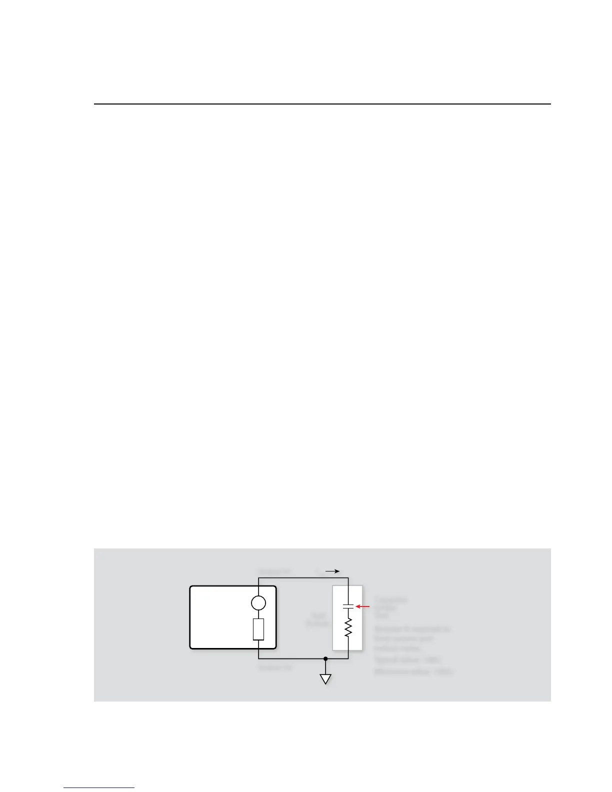
2.4 Capacitor Leakage Test
One important parameter associated with capacitors is leakage
current. Once the leakage current is known, the insulation resist-
ance can be easily calculated. The amount of leakage current in
a capacitor depends both on the type of dielectric as well as the
applied voltage. With a test voltage of 100V, for example, ceramic
dielectric capacitors have typical leakage currents in the nanoamp
to picoamp range, while polystyrene and polyester dielectric
capacitors exhibit a much lower leakage current—typically in the
femtoamp (10
–15
A) range
2.4.1 Test Configuration
Figure 2-3 shows the test configuration for the capacitor leakage
test. The instrument sources the test voltage across the capacitor,
and it measures the resulting leakage current through the device.
The resistor, R, is included for current limiting, and it also helps
to reduce noise. A typical value for R is 1MW, although that value
can be decreased for larger capacitor values. Note, however, that
values less than 10kW are not recommended.
2.4.2 Leakage Resistance Calculations
Once the leakage current is known, the leakage resistance can
easily be calculated from the applied voltage and leakage current
value as follows:
R = V/I