3-1
Section 3
Bipolar Transistor Tests
3.1 Introduction
Bipolar transistor tests discussed in this section include: tests to
generate common-emitter characteristic curves, Gummel plot,
current gain, and transistor leakage tests.
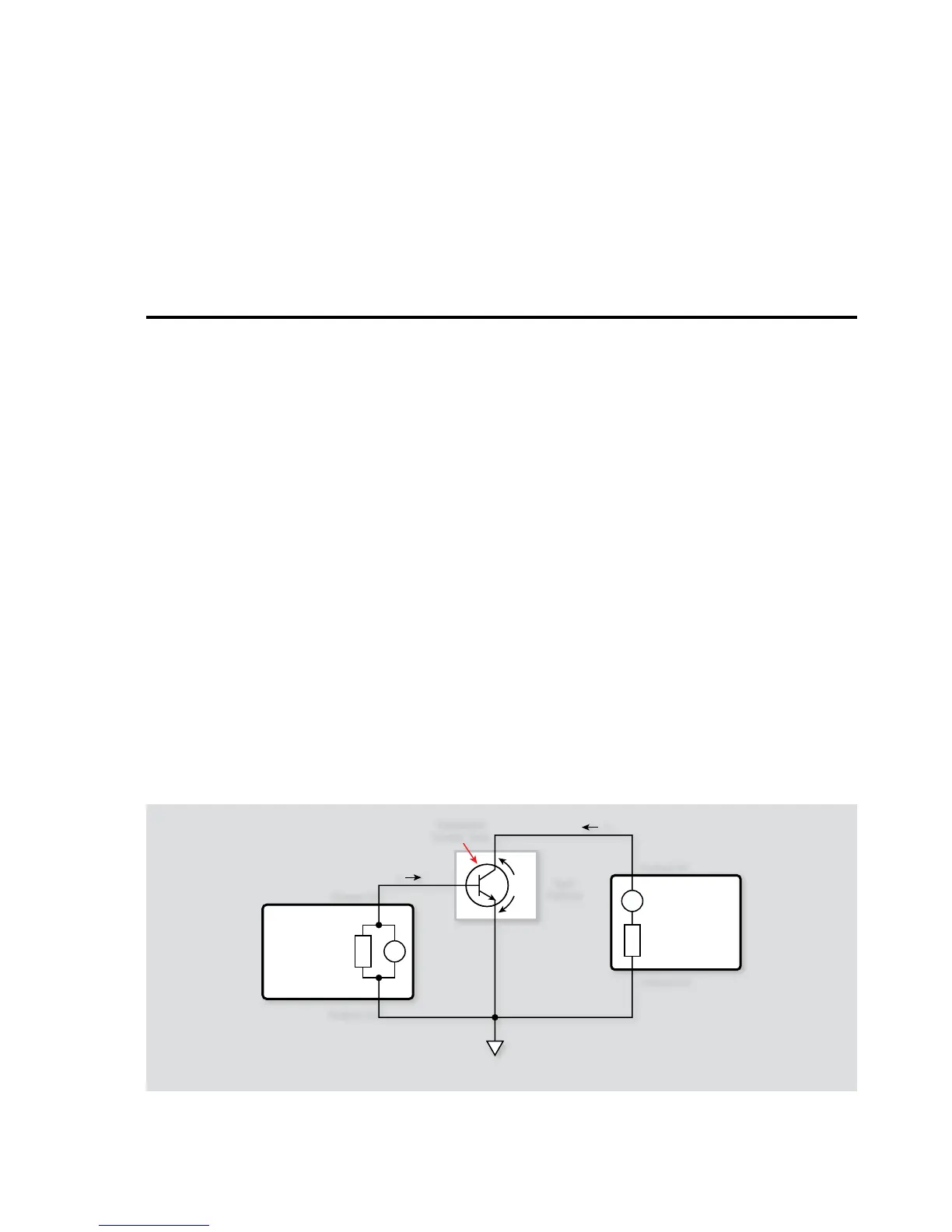
3.2 Instrument Connections
Figure 3-1 shows the instrument connections for the bipolar
transistor tests outlined in this section. Two Source-Measure
channels are required for the tests (except for the leakage current
test, which requires only one Source-Measure channel).
Keithley Model 2600-BAN cables or Model 7078-TRX-3 low noise
triaxial cables are recommended to make instrument-to-test fix-
ture connections. In addition, the safety interlock connecting
cables must be connected to the instrument and fixture if using
instrumentation capable of producing greater than 42V.
WARNING
Lethal voltages may be exposed when working with
test fixtures. To avoid a possible shock hazard, the
fixture must be equipped with a working safety
interlock circuit. For more information on the
interlock of the Series 2600, please see the Series
2600 Reference Manual.
NOTES
Remote sensing connections are recommended for
optimum accuracy. See paragraph 1.2.2 for details.
If measurement noise is a problem, or for critical, low
level applications, use shielded cable for all signal
connections.
3.3 Common-Emitter
Characteristics
Common-emitter characteristics are probably the most familiar
type of curves generated for bipolar transistors. Test data used to
generate these curves is obtained by sweeping the base current
(I
B
) across the desired range of values at specific increments. At
each be current value, the collector-emitter voltage (V
CE
) is swept
across the desired range, again at specific increments. At each V
CE
value, the collector current (I
C
) is measured.
Once the data is collected, it is conveniently printed (if using TSB).
You can then use the copy-and-paste method to place the data
into a spreadsheet program such as Microsoft Excel. Common
 Loading...


