5-2
SECTION 5
Using Substrate Bias
A test fixture with appropriate shielding and safety interlock
mechanisms is recommended for test connections, along with
Model 7078-TRX-3 triax cables for low current measurements.
Note that the connecting cables to the second instrument, assume
that local sensing will be used even though that may not be the
situation in many cases.
5.2.2 Voltage Source Substrate Bias
Connections
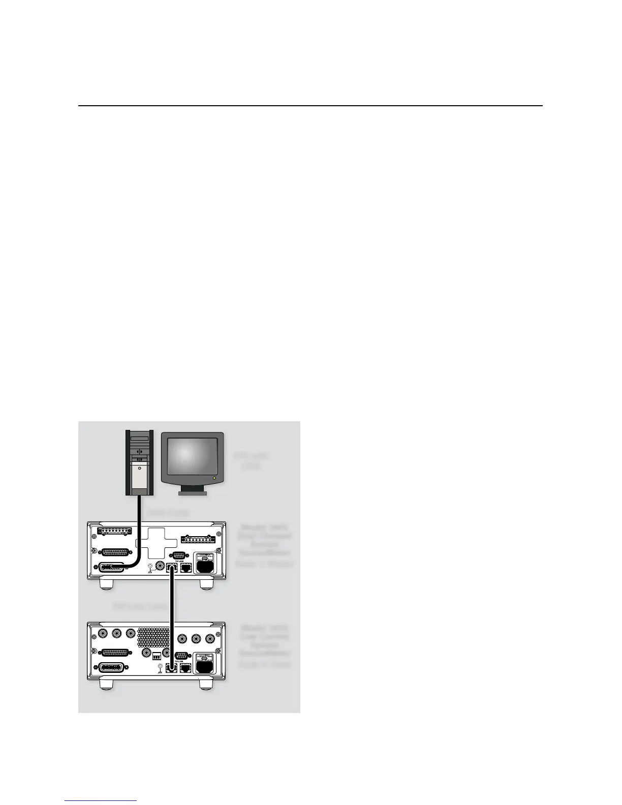
Figure 5-2 shows bias connections using a single-channel Model
2635 Low Current System SourceMeter instrument for substrate
bias connections. Two additional SMU channels are added using
a dual-channel Model 2602 System SourceMeter instrument. Note
that remote sensing is not used in this application; remote sensing
could be added by connecting the sense terminals of the Model
2635 to the sense connections on the test fixture and adding addi-
tional remote sense commands to the program.
NOTES
Remote sensing connections are recommended for
optimum accuracy. See paragraph 1.2.2 for details.
If measurement noise is a problem or for critical, low
level applications, use shielded cable for all signal
connections.
5.3 Source-Measure Unit
Substrate Biasing
The following paragraphs discuss using three SMU channels to
provide substrate biasing: a dual-channel instrument, such as a
Model 2602 or 2636, and a single-channel instrument, such as
a 2601 or 2635. All of the example programs will work with two
dual-channel instruments with no modification.
In the first example, the substrate current (I
SB
) is measured as the
gate-source voltage (V
GS
) is swept across the desired range. The
program generates a plot of I
SB
vs. V
GS
. In the second example, the
third SMU channel provides substrate bias for common-source
characteristic tests.
5.3.1 Program 12 Test Configuration
Figure 5-3 shows the test configuration for Program 12. SMUB of
Node 1 is used to sweep V
GS
, while SMUA of Node 1 sources V
DS
.
SMUA of Node 2 applies a user-defined substrate bias (V
SB
) to the
device under test: it also measures the substrate current (I
SB
).
5.3.2 Example Program 12: Substrate
Current vs. Gate-Source Voltage
Program 12 demonstrates methods to generate an I
SB
vs. V
GS
plot.
Follow these steps to use this program.
With the power off, connect the dual-channel Instrument to 1.
the computer’s IEEE-488 interface. Connect the single-channel
Instrument to the dual-channel master using a crossover Eth-
ernet cable.
Connect the test fixture to both units using appropriate 2.
c a b l e s .
Turn on the instruments and allow the units to warm up for 3.
two hours for rated accuracy.
Configure the TSP-Link communications for each instrument.4.
Slave: A single-channel instrument such as the Model 2601,
2611, or 2635.
1. Press the MENU key to access MAIN MENU.
2. Select the COMMUNICATION menu. (Skip this step if the
Series 2600 instruments used have firmware Revision 1.4.0
or later installed.)
 Loading...


