5-4
SECTION 5
Using Substrate Bias
vgsstart
• represents the start value for the gate-source
voltage sweep
vgsstop
• represents the stop value for the gate-source
voltage sweep
vgssteps
• represents the number of steps in the sweep
If these values are left blank, the function will use the default
values given to the variables, but you can specify each vari-
able value by simply sending a number that is in range in the
function call. As an example, if you wanted the drain-source
voltage (V
DS
) to be 2V, substrate-source (V
SB
) to be –2V, the
gate-source (V
GS
) voltage sweep start value at 1V, the gate-
source sweep stop value at 12V, and the number of steps to
be 15, you would send
FET _ Isb _ Vgs(2, -2, 1, 12,
15)
to the instrument.
The sources will be enabled, and the gate-source voltage 11.
sweep will be executed.
Once the sweep has been completed, the data (I12.
D
, V
GS
, and I
SB
)
will be presented in the Instrument Console window of TSB.
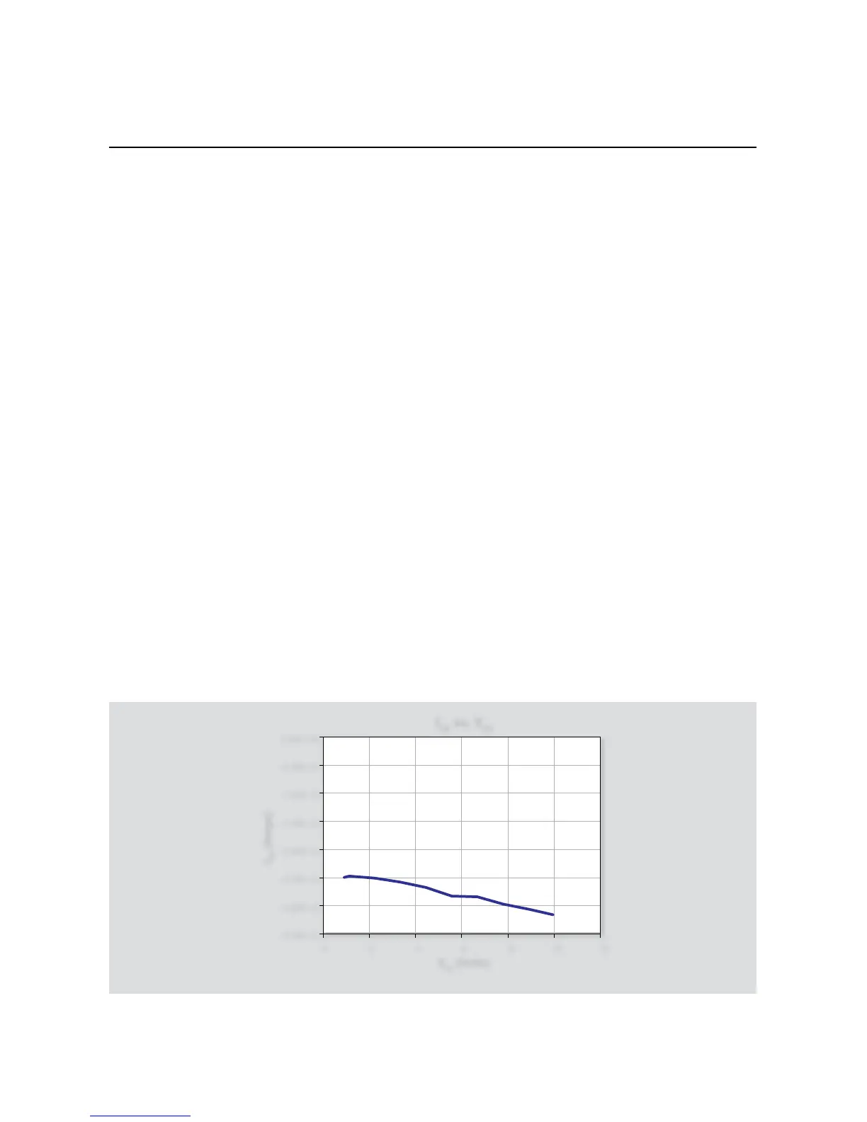
5.3.3 Typical Program 12 Results
Figure 5-4 shows a typical plot generated by example Program 12
using an SD210 MOSFET.
5.3.4 Program 12 Description
After the SMUs are returned to default conditions, Node 1 SMUB,
which sweeps V
GS
, is configured as follows:
Source V•
1µA compliance, autorange•
Local sense•
vgsstart
• : 0V
vgsstop
• : 10V
vgssteps
• : 10
Next, Node 1 SMUA, which sources V
DS
, is set up to operate in the
following manner:
Source V•
Local sensing•
100mA compliance, autorange•
vdssource
• : 1V
Finally, Node 2 SMUA, which sources V
SB
and measures I
SB
, is pro-
grammed as follows:
Source V•
Local sensing•
1 compliance, autorange measure•
1 NPLC Line cycle integration•
After both instruments are set up, the outputs are zeroed and
enabled. The bias values V
SB
and V
DS
are applied, then the V
GS
sweep begins. At each point in the sweep, the drain current (I
D
)
and substrate leakage (I
SB
) are measured.
After the sweep is complete, the data (I
D
, V
GS
, and I
SB
) is printed to
the Instrument Console of TSB.
 Loading...


