EasyManua.ls Logo

Keithley Series 2600 User Manual

Keithley Series 2600
136 pages
To Next Page IconTo Next Page
To Previous Page IconTo Previous Page
Page #48 background imageLoading...
Page #48 background image
5-9
SECTION 5
Using Substrate Bias
istop, isteps, vstart, vstop, vsteps,
vsbsource)
is created.
istart
• represents the start value for the base current
sweep
istop
• represents the stop value for the base current
sweep
isteps
• represents the number of steps in the sweep
vstart
• represents the start value for the collector-
emitter voltage sweep
vstop
• represents the stop value for the collector-emitter
voltage sweep
vsteps
• represents the number of steps in the sweep
vsbsource
• represents the substrate bias voltage
If these values are left blank, the function will use the default
values given to the variables, but you can specify each vari-
able value by simply sending a number that is in-range in the
function call. As an example, if you wanted to have the base
current (I
B
) current sweep start value at 20µA, the base cur-
rent sweep stop value at 200µA and the number of steps to
be 10, the collector-emitter (V
CE
) voltage sweep start value
at 1V, the collector-emitter sweep stop value at 12V and the
number of steps to be 80, and the substrate bias to be –2V, you
would send
BJT _ Comm _ Em t _ Vsb(20E-6,
200E-6, 10, 1, 12, 80, -2)
to the instrument.
The sources will be enabled, and the substrate bias is applied, 10.
the base current value is applied, and the collector-emitter
voltage sweep is executed. The base current value is then
incremented and the collector-emitter sweep is re-run.
Once the gate-source sweep has been completed, the data (I11.
B
,
V
SB
, V
CE
, and I
C
) will be presented in the Instrument Console
window of TSB.
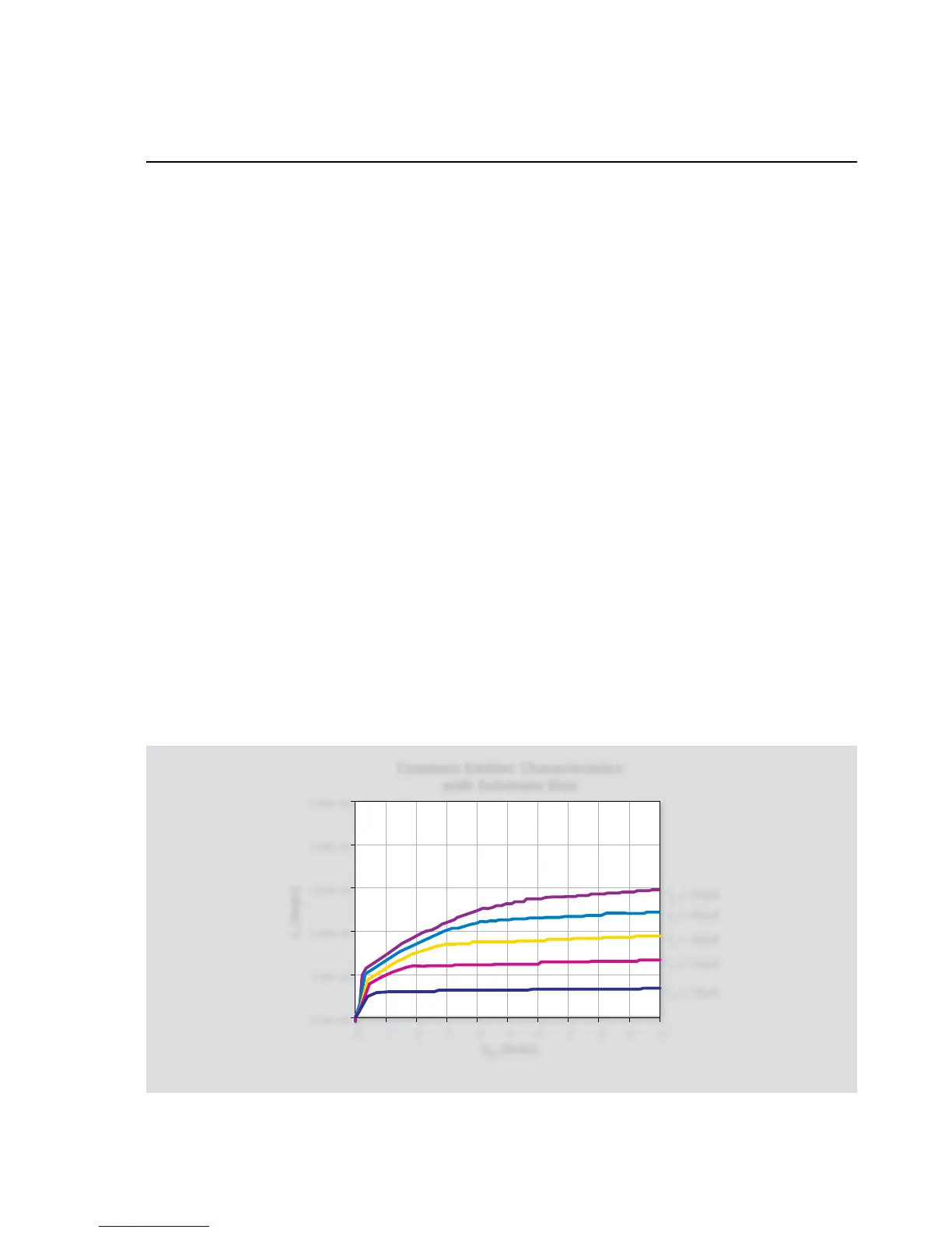
5.4.3 Typical Program 14 Results
Figure 5-8 shows a typical plot generated by example Program 14.
5.4.4 Program 14 Description
After both instruments are returned to default conditions, Node 1
SMUB, which sweeps IB, is configured as follows:
Source I•
IV compliance, 1.1V range•
Local sense•
istart
• : 10µA
istop
• : 5A
isteps
• : 5
Next, Node 1 SMUA, which sweeps V
CE
and measures I
C
, is set up
to operate in the following manner:
Source V•
Local sensing•
100mA compliance, autorange measure•
1 NPLC Line cycle integration•
Figure 5-8. Program 14 typical results: Common-emitter characteristics with substrate bias

Table of Contents

Question and Answer IconNeed help?

Do you have a question about the Keithley Series 2600 and is the answer not in the manual?

Keithley Series 2600 Specifications

General IconGeneral
ModelSeries 2600
Measurement FunctionsVoltage, Current, Resistance, Power
ResolutionUp to 6.5 digits
Current Source RangeUp to 10A
Communication InterfacesGPIB, USB
ApplicationsSemiconductor testing
CategorySource Measure Unit (SMU)
ChannelsSingle or Dual Channel (varies by model)

Summary

Section 1 General Information

1.1 Introduction

Discusses system configurations for application programs.

1.2 Hardware Configuration

Details system hardware configuration.

1.2.1 System Configuration

Describes the overall hardware configuration of a test system.

1.2.2 Remote/Local Sensing Considerations

Discusses sensing methods for optimizing accuracy.

1.3 Graphing

Explains how to visualize data using graphing.

Section 2 Two-terminal Device Tests

2.1 Introduction

Introduces tests for two-terminal devices.

2.2 Instrument Connections

Details instrument connections for two-terminal device tests.

2.3 Voltage Coefficient Tests of Resistors

Explains testing voltage coefficient of resistors.

2.4 Capacitor Leakage Test

Details testing capacitor leakage current.

2.5 Diode Characterization

Explains diode characterization tests.

Section 3 Bipolar Transistor Tests

3.1 Introduction

Introduces bipolar transistor tests.

3.2 Instrument Connections

Details instrument connections for bipolar transistor tests.

3.3 Common-Emitter Characteristics

Explains testing common-emitter characteristics for transistors.

3.4 Gummel Plot

Explains generating Gummel plots for transistors.

3.5 Current Gain

Discusses methods for measuring DC and AC current gain.

3.6 Transistor Leakage Current

Explains testing transistor leakage current.

Section 4 FET Tests

4.1 Introduction

Introduces FET testing.

4.2 Instrument Connections

Details instrument connections for FET tests.

4.3 Common-Source Characteristics

Explains common-source characteristics for FETs.

4.4 Transconductance Tests

Details transconductance testing for FETs.

4.5 Threshold Tests

Explains methods for determining FET threshold voltage.

Section 5 Using Substrate Bias

5.1 Introduction

Introduces substrate bias concepts.

5.2 Substrate Bias Instrument Connections

Details instrument connections for substrate bias.

5.3 Source-Measure Unit Substrate Biasing

Discusses SMU substrate biasing methods.

5.4 BJT Substrate Biasing

Explains substrate bias for BJTs.

Section 6 High Power Tests

6.1 Introduction

Introduces high power testing challenges.

6.1.1 Program 15 Test Configuration

Details test setup for high current tests.

6.1.2 Example Program 15: High Current Source and Voltage Measure

Shows high current sourcing with voltage measurement.

6.2 Instrument Connections

Details instrument connections for high power tests.

6.2.1 Program 16 Test Configuration

Details test setup for high voltage tests.

6.2.2 Example Program 16: High Voltage Source and Current Measure

Shows high voltage sourcing with current measurement.

Appendix A Scripts

Two-Terminal Device Scripts

Contains scripts for two-terminal device tests.

Bipolar Transistor Scripts

Contains scripts for bipolar transistor tests.

High Power Test Scripts

Contains scripts for high power tests.

FET Test Scripts

Contains scripts for FET tests.

Substrate Bias Scripts

Contains scripts for substrate bias tests.

Related product manuals