4-2
SECTION 4
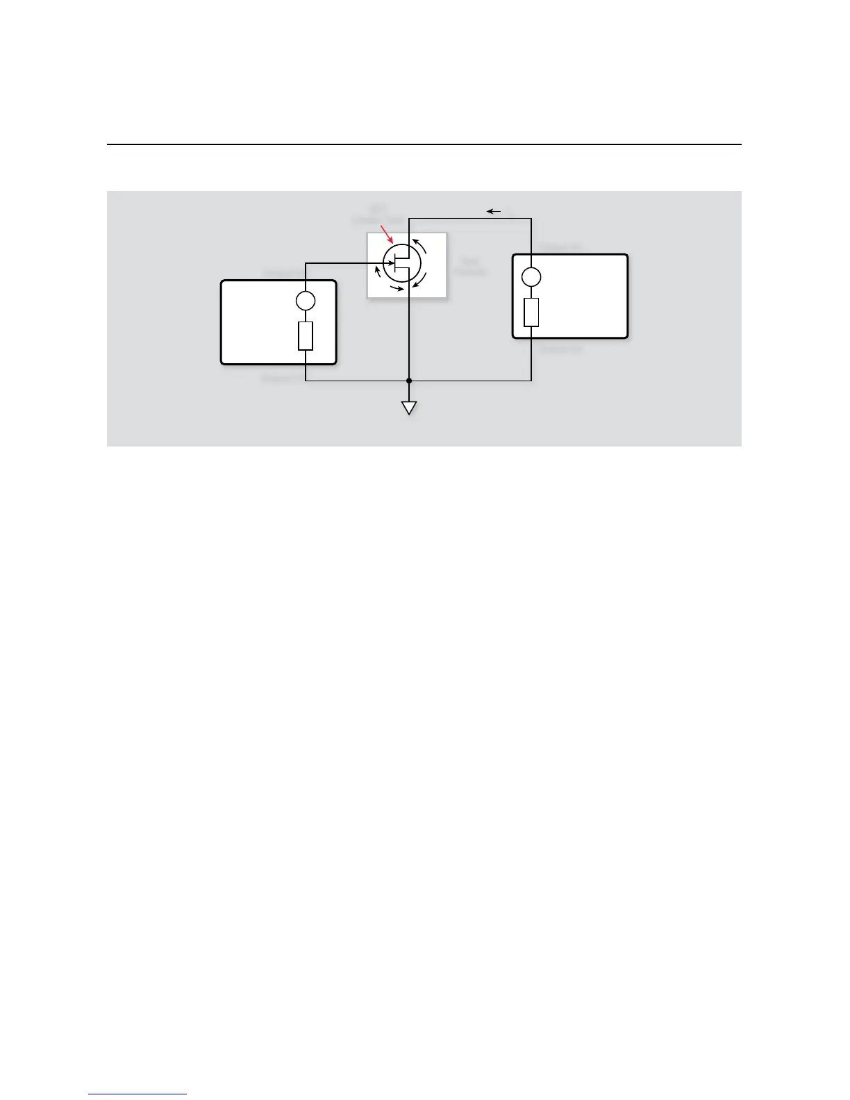
FET Tests
Install an N-channel FET such as an SD210 in the appropriate 6.
transistor socket of the test fixture.
Now, we must send the code to the instrument. The simplest 7.
method is to right-click in the open script window of TSB,
and select ‘Run as TSP file’. This will compile the code and
place it in the volatile run-time memory of the instrument.
To store the program in non-volatile memory, see the “TSP
Programming Fundamentals” section of the Series 2600 Refer-
ence Manual.
Once the code has been placed in the instrument run-time 8.
memory, we can run it at any time simply by calling the func-
tion ‘
FET _ Comm _ Source()
’. This can be done by typing
the text ‘
FET _ Comm _ Source()
’ after the active prompt
in the Instrument Console line of TSB.
In the program ‘9. FET_Comm_Source.tsp’, the function
FET _
Comm _ Source(vgsstart, vgsstop, vgssteps,
vdsstart, vdsstop, vdssteps)
is created.
vgsstart
• represents the initial voltage value in the
gate-source V
GS
sweep
vgsstop
• represents the final voltage value in the gate-
source V
GS
sweep
vgssteps
• represents the number of steps in the sweep
vdsstart
• represents the initial voltage value in the
drain-source V
DS
sweep
vdsstop
• represents the final voltage value in the drain-
source V
DS
sweep
vdssteps
• represents the number of steps in the sweep
If these values are left blank, the function will use the default
values given to the variables, but you can specify each vari-
able value by simply sending a number that is in-range in
the function call. As an example, if you wanted to have the
start voltages for V
GS
and V
DS
sweeps be 1V, the stop value
be 11V, and the number of steps be 20, you would send
FET _ Comm _ Source(1, 11, 20, 1, 11, 20)
to
the instrument.
The sources will be zeroed and then enabled. The program 10.
will execute a sweep of V
GS
values between 0V and 10V using
2V steps. At each V
GS
step, V
DS
will be stepped between 0V
and 10V at 0.1V increments. At each increment, I
D
will be
measured.
Once the measurements have been completed, the data (V11.
GS
,
V
DS
, and I
DS
) will be presented in the Instrument Console
window of TSB.
4.3.3 Typical Program 9 Results
Figure 4-2 shows a typical plot generated by example Program 9.
A 2N4392 N-channel JFET was used to generate these curves.
4.3.4 Program 9 Description
The unit is returned to default conditions. Next, SMUB, which
sweeps V
GS
, is programmed as follows:
Source V•
1mA compliance, 1mA range•
Local sense•
vgsstart
• : 0V
vgsstop
• : 10V
vgssteps
• : 5
SMUA, which sweeps V
DS
and measures I
D
, is configured as
follows: