3-4
SECTION 3
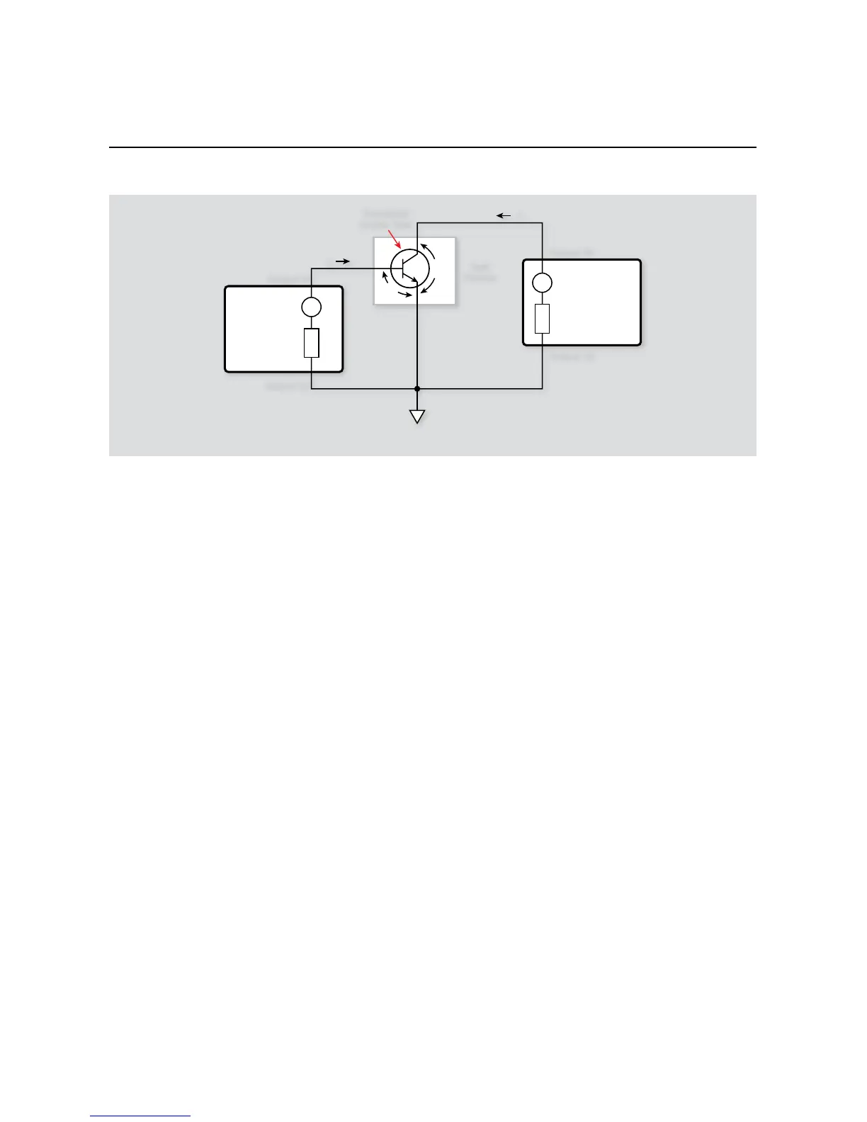
Bipolar Transistor Tests
measures I
B
. SMUA sets V
CE
to the desired fixed value, and it also
measures I
C
.
Due to the low current measurements associated with this type of
testing, the Keithley Model 2636 System SourceMeter instrument
is recommended. Its low level current measurement capabilities
and dual-channel configuration are ideal for producing high
quality Gummel plots of transistors.
3.4.2 Measurement Considerations
As written, the range of V
BE
test values is from 0V to 0.7V in 0.01V
increments. It may be necessary, however, to change these limits
for best results with your particular device. Low currents will be
measured so take the usual low current precautions.
3.4.3 Example Program 5: Gummel Plot
Program 5 demonstrates the basic programming techniques
for generating a Gummel plot. Follow these steps to run this
program:
With the power off, connect a dual-channel System Source-1.
Meter instrument to the computer’s IEEE-488 interface.
Connect the test fixture to both units using appropriate 2.
c a b l e s .
Turn on the instrument and allow the unit to warm up for two 3.
hours for rated accuracy.
Turn on the computer and start Test Script Builder (TSB). Once 4.
the program has started, open a session by connecting to the
instrument. For details on how to use TSB, see the Series 2600
Reference Manual.
You can simply copy and paste the code from Appendix A in 5.
this guide into the TSB script editing window (Program 5),
manually enter the code from the appendix, or import the TSP
file ‘Gummel.tsp’ after downloading it to your PC.
If your computer is currently connected to the Internet, you
can click on this link to begin downloading: http://www.
keithley.com/data?asset=50918
Install an NPN transistor such as a 2N5089 in the appropriate 6.
transistor socket of the test fixture.
Now, we must send the code to the instrument. The simplest 7.
method is to right-click in the open script window of TSB,
and select ‘Run as TSP file’. This will compile the code and
place it in the volatile run-time memory of the instrument.
To store the program in non-volatile memory, see the “TSP
Programming Fundamentals” section of the Series 2600 Refer-
ence Manual.
Once the code has been placed in the instrument run-time 8.
memory, we can run it at any time simply by calling the
function ‘Gummel()’. This can be done by typing the text
‘
G u m m e l()
’ after the active prompt in the Instrument Con-
sole line of TSB.
In the program ‘Gummel.tsp’, the function 9.
Gummel
(vbestart, vbestop, vbesteps, vcebias)
is
created.
vbestart
• represents the sweep start voltage value on
the base of the transistor
vbestop
• represents the sweep stop value
vbesteps
• is the number of steps in the base
voltage sweep