2-5
SECTION 2
Two-terminal Device Tests
2.4.6 Program 2 Description
At the start of the program, the instrument is reset to default con-
ditions, the error queue, and data storage buffers are cleared. The
following configuration is then applied before the data collection
begins:
Source V, DC mode•
Local sense•
10mA compliance, autorange measure•
1 NPLC Line cycle integration•
vsrc:
• 40V
The instrument then sources
vsrc
, checks the source for compli-
ance in the function named
Check _ Comp()
, and performs a
measurement of the current if compliance is false.
The function
Calc _ Val()
then performs the calculation of
the leakage resistance based on the programmed source value
and the measured current value as described in paragraph 2.4.2,
Leakage Resistance Calculations.
The instrument output is then turned off and the function
Print _ Data()
is run to print the data to the TSB window.
Note: If the compliance is true, the instrument will abort the pro-
gram and print a warning to the TSB window. Check the DUT
and cabling to make sure everything is connected correctly and
re-run the test.
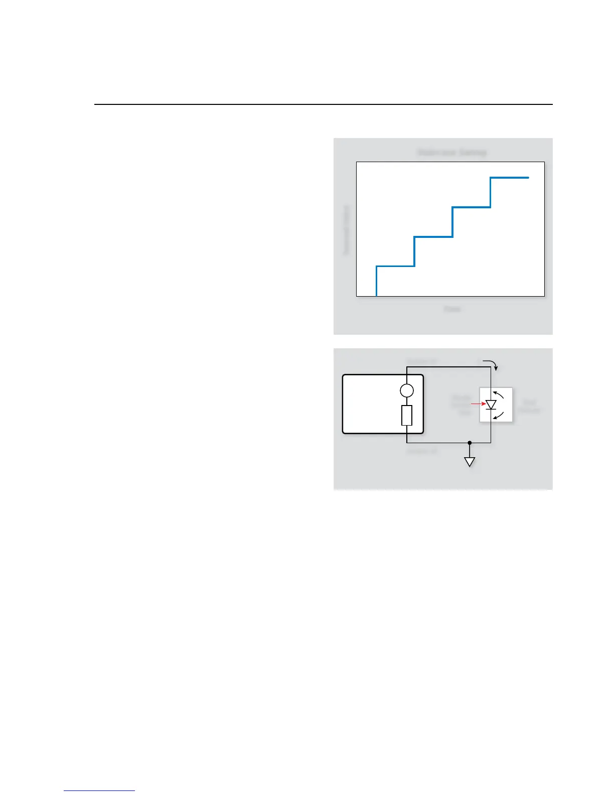
2.5 Diode Characterization
The System SourceMeter instrument is ideal for characterizing
diodes because it can source a current through the device, and
measure the resulting forward voltage drop (V
F
) across the device.
A standard technique for diode characterization is to perform a
staircase sweep (Figure 2-4) of the source current from a starting
value to an end value while measuring the voltage at each current
step. The following paragraphs discuss the test configuration and
give a sample test program for such tests.
2.5.1 Test Configuration
Figure 2-5 shows the test configuration for the diode character-
ization test. The System SourceMeter instrument is used to source
the forward current (I
F
) through the diode under test, and it also
measures the forward voltage (V
F
) across the device. I
F
is swept
across the desired range of values, and V
F
is measured at each cur-
rent. Note that the same general configuration could be used to
measure leakage current by reversing the diode, sourcing voltage,
and measuring the leakage current.
2.5.2 Measurement Considerations
Because the voltages being measured will be fairly small (≈0.6V),
remote sensing can be used to minimize the effects of voltage
drops across the test connections and in the test fixture. Remote
sensing requires the use of the Sense connections on the System
SourceMeter channel being used, as well as changing the code to
reflect remote sensing. For more information on remote sensing,
see the Series 2600 Reference Manual.
2.5.3 Example Program 3:
Diode Characterization
Program 3 demonstrates the basic programming techniques for
running the diode characterization test. Follow these steps to use
this program: