5-3
SECTION 5
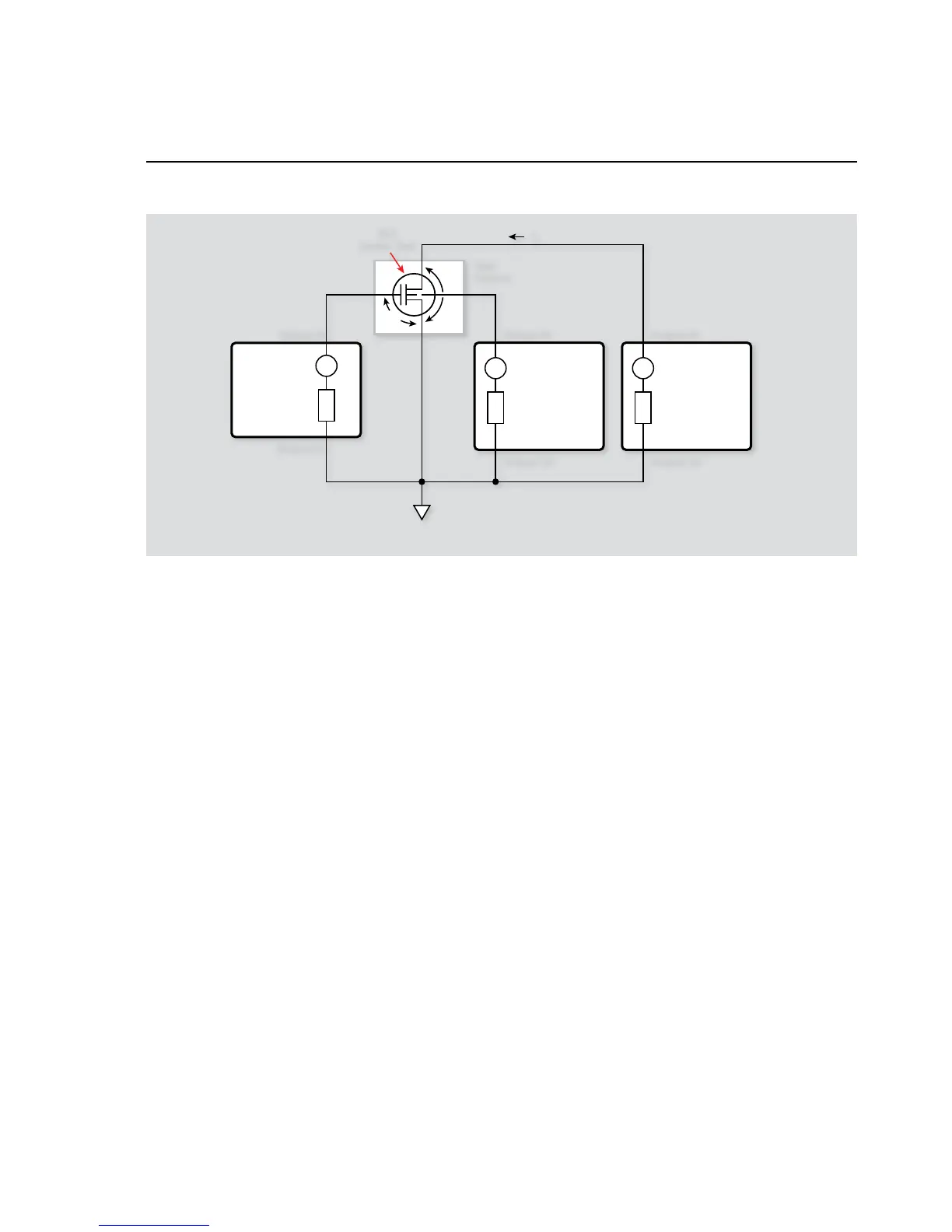
Using Substrate Bias
3. Select the TSPLINK_CFG menu. (If the Series 2600 instru-
ments used have firmware Revision 1.4.0 or later installed,
the menu name should be TSPLINK.)
4. Select the NODE menu.
5. Set the NODE number to 2 and press ENTER.
Master: A dual-channel instrument such as the Model 2602,
2612, or 2636.
1. Press the MENU key to access MAIN MENU.
2. Select the COMMUNICATION menu. (Skip this step if
the Series 2600 instruments used have firmware Revision
1.4.0 or later installed.)
3. Select the TSPLINK_CFG menu. (If the Series 2600
instruments used have firmware Revision 1.4.0 or later
installed, the menu name should be TSPLINK.)
4. Select the NODE menu.
5. Set the NODE number to 1 for the master and press
ENTER.
6. Select the TSPLINK_CFG menu. (If the Series 2600
instruments used have firmware Revision 1.4.0 or later
installed, the menu name should be TSPLINK.)
7. Select the RESET to initialize the TSP-Link.
Turn on the computer and start Test Script Builder (TSB). 5.
Once the program has started, open a session by connecting
to the master instrument. For details on how to use TSB, see
the Series 2600 Reference Manual.
You can simply copy and paste the code from Appendix A in 6.
this guide into the TSB script editing window (Program 12),
manually enter the code from the appendix, or import the TSP
file ‘FET_ Isb_Vgs .tsp’ after downloading it to your PC.
If your computer is currently connected to the Internet, you
can click on the following link to begin downloading: http://
www.keithley.com/data?asset=50964.
Install an NPN FET such as a SD210 in the appropriate tran-7.
sistor socket of the test fixture.
Now, we must send the code to the instrument. The simplest 8.
method is to right-click in the open script window of TSB and
select ‘Run as TSP file’. This will compile the code and place
it in the volatile run-time memory of the instrument. To store
the program in non-volatile memory, see the “TSP Program-
ming Fundamentals” section of the Series 2600 Reference
Manual.
Once the code has been placed in the instrument run-time 9.
memory, we can run it at any time simply by calling the func-
tion ‘FET_Isb_Vgs()’. This can be done by typing the text
‘
FET _ Isb _ Vgs()
’ after the active prompt in the Instru-
ment Console line of TSB.
In the program ‘10. FET_ Isb_Vgs ( ).tsp’, the function
FET _ Isb _
Vgs(vdssource, vsbsource,vgsstart,vgsstop,
vgssteps)
is created.
vdssource
• represents the voltage value on the drain-
source of the transistor
vsbsource
• represents the voltage value on the
substrate-source of the transistor