1-2
SECTION 1
General Information
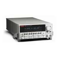
on the digital I/O port on the Models 2601 and 2602
System SourceMeter instruments is not suitable for
control of safety circuits and should not be used to
control a safety interlock. The Interlock pin on the
digital I/O port for the Models 2611, 2612, 2635, and
2636 can be used to control a safety interlock.
Computer: The test programs in this document require a PC with
IEEE-488 (GPIB) communications and cabling.
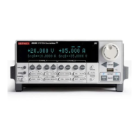
Software: Series 2600 System SourceMeter instruments each
use a powerful on-board test sequencer known as the Test Script
Processor (TSP™). The TSP is accessed through the instrument
communications port, most often, the GPIB. The test program, or
script, is simply a text file that contains commands that instruct
the instrument to perform certain actions. Scripts can be written
in many different styles as well as utilizing different programming
environments. This guide discusses script creation and manage-
ment using Keithley Test Script Builder (TSB), an easy-to-use pro-
gram that allows you to create, edit, and manage test scripts. For
more information on TSB and scripting, see Section 2: Using Test
Script Builder of the Series 2600 Reference Manual.
Connections and Cabling: High quality cabling, such as the
Keithley Model 2600-BAN or Model 7078-TRX-3 triaxial cables,
should be used whenever possible.
1.2.2 Remote/Local Sensing
Considerations
In order to simplify the test connections, most applications in
this guide use local sensing for the SMUs. Local sensing requires
connecting only two cables between the SMUs and the test fixture
(OUTPUT HI and OUTPUT LO).
When sourcing and/or measuring voltage in a low impedance
test circuit, there can be errors associated with IR drops in the
test leads. Using four-wire remote sense connections optimizes
voltage source and measure accuracy. When sourcing voltage,
four-wire remote sensing ensures that the programmed voltage is
delivered to the DUT. When measuring voltage, only the voltage
drop across the DUT is measured. Use four-wire remote sensing
for the following source-measure conditions:
Sourcing and/or measuring voltage in low impedance (<1k• W)
test circuits.
Enforcing voltage compliance limit directly at the DUT.•
1.3 Graphing
All of the programs in this guide print the data to the TSB Instru-
ment Console. In some cases, graphing the data can help you visu-
alize the characteristics of the DUT. One method of graphing is to
copy and paste the data from the TSB Instrument Console and
place it in a spreadsheet program such as Microsoft Excel.
After the script has run, and the data has been returned to the
Instrument Console, you can highlight it by using the PC’s mouse:
depress the Control and c (commonly written as Ctrl+c) keys on
the keyboard simultaneously, switch to an open Excel worksheet,
and depress Control and v simultaneously (Ctrl+v). The data
should now be placed in the open worksheet columns so you can
use the normal graphing tools available in your spreadsheet pro-
gram to graph the data as needed.
This Applications Guide is designed for Series 2600 instrument users who want to create their own scripts using the Test Script
Builder software. Other options include LabTracer
®
2 software, the Automated Characterization Suite (ACS), and a LabVIEW driver.

 Loading...
