2- 6
SECTION 2
Two-terminal Device Tests
With the power off, connect the instrument to the computer’s 1.
IEEE-488 interface.
Connect the test fixture to the instrument using appropriate 2.
cables.
Turn on the instrument, and allow the unit to warm up for 3.
two hours for rated accuracy.
Turn on the computer and start Test Script Builder (TSB). Once 4.
the program has started, open a session by connecting to the
instrument. For details on how to use TSB, see the Series 2600
Reference Manual.
You can simply copy and paste the code from Appendix A in 5.
this guide into the TSB script editing window (Program 3A,
Diode Forward Characterization), manually enter the code
from the appendix, or import the TSP file ‘Diode_Fwd_Char.
tsp’ after downloading it to your PC.
If your computer is currently connected to the Internet, you
can click on this link to begin downloading: http://www.
keithley.com/data?asset=50924.
Install a small-signal silicon diode such as a 1N914 or 1N4148 6.
in the appropriate axial socket of the test fixture.
Now, we must send the code to the instrument. One method 7.
is simply to right-click in the open script window of TSB, and
select ‘Run as TSP file’. This will compile the code and place
it in the volatile run-time memory of the instrument. To store
the program in non-volatile memory, see the “TSP Program-
ming Fundamentals” section of the Series 2600 Reference
Manual.
Once the code has been placed in the instrument run-time 8.
memory, we can run it at any time simply by calling the func-
tion ‘Diode_Fwd_Char()’. This can be done by typing the text
‘
Diode _ F wd _ Char()
’ after the active prompt in the
Instrument Console line of TSB.
In the program ‘Diode_Fwd_Char.tsp’, the function 9.
Diode _
Fwd _ Char(ilevel, start, stop, steps)
is
created. The variable
ilevel
represents the current value
applied to the device-under-test (DUT) both before and after
the staircase sweep has been applied. The
start
variable
represents the starting current value for the sweep, stop repre-
sents the end current value, and steps represents the number
of steps in the sweep. If any values are left blank, the function
will use the default value given to that variable, but you can
specify what voltage is applied by simply sending a voltage that
is in-range in the function call.
As an example, if you wanted to configure a test that would 10.
source 0mA before and after the sweep, with a sweep start
value of 1mA, stop value of 10mA, and 10 steps, you would
simply send
Diode _ Fwd _ Char(0, 0.001, 0.01,
10)
to the instrument.
The instrument will then source the programmed current 11.
staircase sweep and measure the respective voltage at each
step. The measured and sourced values are then printed to
the screen (if using TSB). To graph the results, simply copy
and paste the data into a spreadsheet such as Microsoft Excel
and chart.
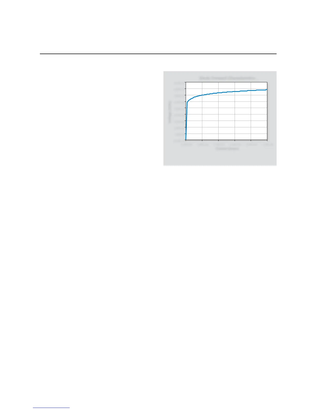
2.5.4 Typical Program 3 Results
Figure 2-6 shows typical results obtained using Example Program
3. These results are for a 1N914 silicon diode.
2.5.5 Program 3 Description
At the start of the program, the instrument is reset to default con-
ditions, the error queue, and data storage buffers are cleared. The
following configuration is then applied before the data collection
begins:
Source I•
Local sense•
10V compliance, autorange measure•
Ilevel:
• 0A
start:
• 0.001A
stop:
• 0.01A
steps:
• 10
The instrument then sources
ilevel
, dwells
l _ delay
sec-
onds, and begins the staircase sweep from
start
to
stop
in
steps. At each current step, both the current and voltage are
measured.
 Loading...


