EasyManua.ls Logo

Keithley Series 2600 User Manual

Keithley Series 2600
136 pages
To Next Page IconTo Next Page
To Previous Page IconTo Previous Page
Page #44 background imageLoading...
Page #44 background image
5-5
SECTION 5
Using Substrate Bias
5.3.5 Modifying Program 12
For different sweeps, the variables for V
GS
start, V
GS
stop, and
V
GS
step values can be changed as required. For different sweep
lengths, array size and loop counter values must be adjusted
accordingly. You can also change the V
DS
value, if desired, by
modifying that parameter accordingly.
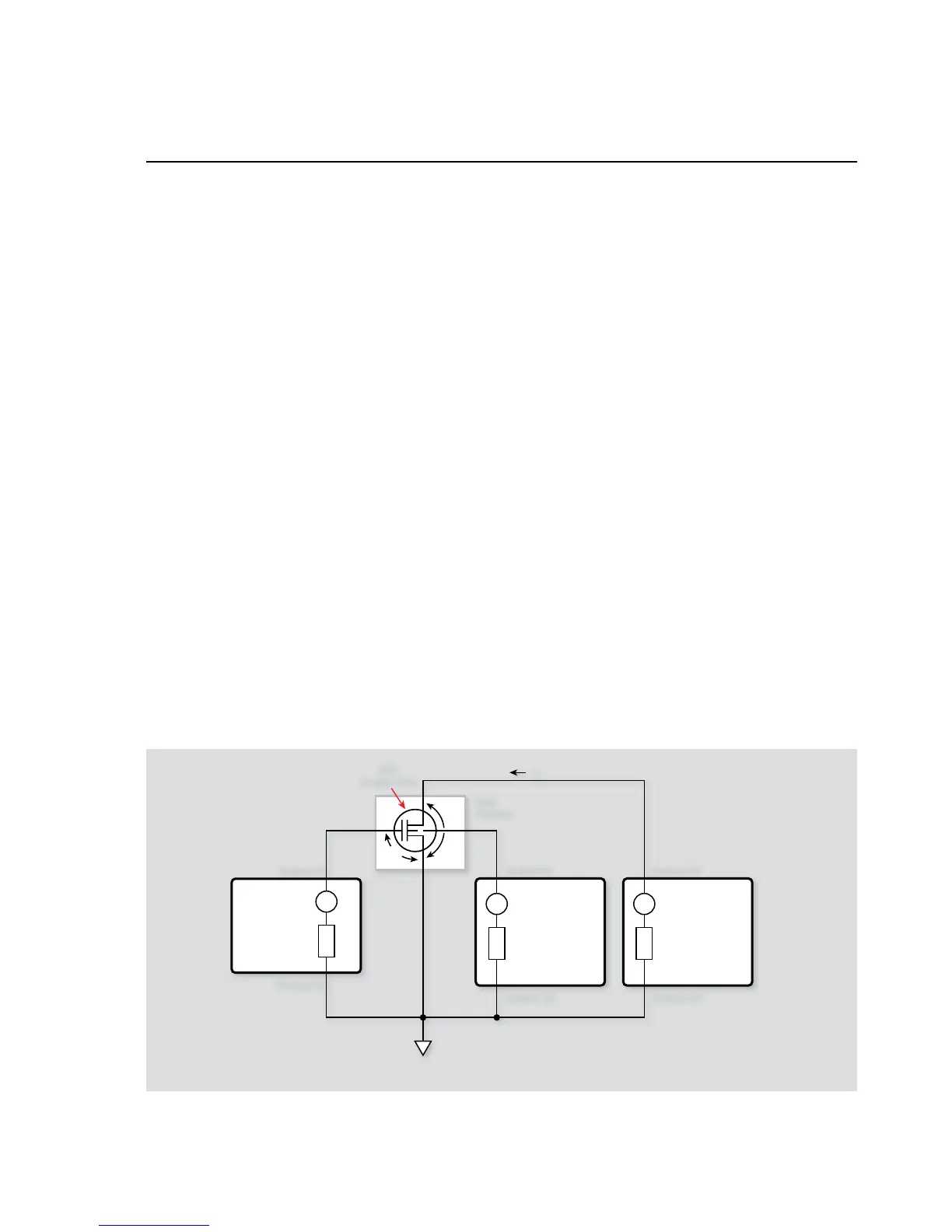
5.3.6 Program 13 Test Configuration
Figure 5-5 shows the test configuration for Program 13. Unit #1
is used to sweep V
GS
; Unit #2 sweeps V
DS
and measures I
D
. Unit
#3 applies a user-defined substrate bias to the device under test.
Common source characteristics are generated by data taken when
the program is run.
5.3.7 Example Program 13:
Common-Source Characteristics
with Source-Measure Unit
Substrate Bias
Program 13 demonstrates common-source characteristic test
pro gram ming with substrate bias. Follow these steps to use this
p r o g r a m .
With the power off, connect the dual-channel SourceMeter 1.
instrument to the IEEE-488 interface of the computer. Con-
nect the single-channel SourceMeter instrument to the dual-
channel master using a crossover Ethernet cable.
Connect the test xture to both units using appropriate 2.
c a b l e s .
Turn on the instruments and allow the units to warm up for 3.
two hours for rated accuracy.
Configure the TSP-Link communications for each instrument.4.
Slave: A single-channel instrument such as the Model 2601,
2611, or 2635.
1. Press the MENU key to access MAIN MENU.
2. Select the COMMUNICATION menu. (Skip this step if the
Series 2600 instruments used have firmware Revision 1.4.0
or later installed.)
3. Select the TSPLINK_CFG menu. (If the Series 2600 instru-
ments used have firmware Revision 1.4.0 or later installed,
the menu name should be TSPLINK.)
4. Select the NODE menu.
5. Set the NODE number to 2 and press ENTER.
Master: A dual-channel instrument such as the Model 2602,
2612, or 2636.
1. Press the MENU key to access MAIN MENU.
2. Select the COMMUNICATION menu. (Skip this step if
the Series 2600 instruments used have firmware Revision
1.4.0 or later installed.)
3. Select the TSPLINK_CFG menu. (If the Series 2600
instruments used have firmware Revision 1.4.0 or later
installed, the menu name should be TSPLINK.)
4. Select the NODE menu.
5. Set the NODE number to 1 for the master and press
ENTER.
I
V
I
V
Series 2600
System
SourceMeter
Channel A
Node 1
Sweeps V
DS
Measures I
D
I
V
Series 2600
System
SourceMeter
Channel A
Node 2
Sources
Substrate Bias
Series 2600
System
SourceMeter
Channel B
Node 1
Sweeps V
GS
V
DS
V
GS
Test
Fixture
FET
Under Test
Output HI Output HI
Output LO
Output LO
I
D
Output HI
Output LO
Figure 5-5. Program 13 test configuration

Table of Contents

Question and Answer IconNeed help?

Do you have a question about the Keithley Series 2600 and is the answer not in the manual?

Keithley Series 2600 Specifications

General IconGeneral
ModelSeries 2600
Measurement FunctionsVoltage, Current, Resistance, Power
ResolutionUp to 6.5 digits
Current Source RangeUp to 10A
Communication InterfacesGPIB, USB
ApplicationsSemiconductor testing
CategorySource Measure Unit (SMU)
ChannelsSingle or Dual Channel (varies by model)

Summary

Section 1 General Information

1.1 Introduction

Discusses system configurations for application programs.

1.2 Hardware Configuration

Details system hardware configuration.

1.2.1 System Configuration

Describes the overall hardware configuration of a test system.

1.2.2 Remote/Local Sensing Considerations

Discusses sensing methods for optimizing accuracy.

1.3 Graphing

Explains how to visualize data using graphing.

Section 2 Two-terminal Device Tests

2.1 Introduction

Introduces tests for two-terminal devices.

2.2 Instrument Connections

Details instrument connections for two-terminal device tests.

2.3 Voltage Coefficient Tests of Resistors

Explains testing voltage coefficient of resistors.

2.4 Capacitor Leakage Test

Details testing capacitor leakage current.

2.5 Diode Characterization

Explains diode characterization tests.

Section 3 Bipolar Transistor Tests

3.1 Introduction

Introduces bipolar transistor tests.

3.2 Instrument Connections

Details instrument connections for bipolar transistor tests.

3.3 Common-Emitter Characteristics

Explains testing common-emitter characteristics for transistors.

3.4 Gummel Plot

Explains generating Gummel plots for transistors.

3.5 Current Gain

Discusses methods for measuring DC and AC current gain.

3.6 Transistor Leakage Current

Explains testing transistor leakage current.

Section 4 FET Tests

4.1 Introduction

Introduces FET testing.

4.2 Instrument Connections

Details instrument connections for FET tests.

4.3 Common-Source Characteristics

Explains common-source characteristics for FETs.

4.4 Transconductance Tests

Details transconductance testing for FETs.

4.5 Threshold Tests

Explains methods for determining FET threshold voltage.

Section 5 Using Substrate Bias

5.1 Introduction

Introduces substrate bias concepts.

5.2 Substrate Bias Instrument Connections

Details instrument connections for substrate bias.

5.3 Source-Measure Unit Substrate Biasing

Discusses SMU substrate biasing methods.

5.4 BJT Substrate Biasing

Explains substrate bias for BJTs.

Section 6 High Power Tests

6.1 Introduction

Introduces high power testing challenges.

6.1.1 Program 15 Test Configuration

Details test setup for high current tests.

6.1.2 Example Program 15: High Current Source and Voltage Measure

Shows high current sourcing with voltage measurement.

6.2 Instrument Connections

Details instrument connections for high power tests.

6.2.1 Program 16 Test Configuration

Details test setup for high voltage tests.

6.2.2 Example Program 16: High Voltage Source and Current Measure

Shows high voltage sourcing with current measurement.

Appendix A Scripts

Two-Terminal Device Scripts

Contains scripts for two-terminal device tests.

Bipolar Transistor Scripts

Contains scripts for bipolar transistor tests.

High Power Test Scripts

Contains scripts for high power tests.

FET Test Scripts

Contains scripts for FET tests.

Substrate Bias Scripts

Contains scripts for substrate bias tests.

Related product manuals