EasyManua.ls Logo

Keithley Series 2600 User Manual

Keithley Series 2600
136 pages
To Next Page IconTo Next Page
To Previous Page IconTo Previous Page
Page #37 background imageLoading...
Page #37 background image
4-8
SECTION 4
FET Tests
WARNING
When a System SourceMeter instrument is pro-
grammed for remote sensing, hazardous voltage
may be present on the SENSE and OUTPUT termi-
nals when the unit is in operate regardless of the
programmed voltage or current. To avoid a pos-
sible shock hazard, always turn off power before
connecting or disconnecting cables to the Source-
Measure Unit or the associated test fixture.
NOTE
Entered values for both V
DS
and I
D
are adjusted to the
reverse polarity because of the connection configura-
tion used. For example, for an N-channel FET, both V
DS
and I
D
must be negative.
As an example, entering a V
DS
of 5V will result in –5V
actually being applied at the output.
These values will result in proper biasing of the
DUT. Also, the sign of the measured V
T
value will be
reversed.
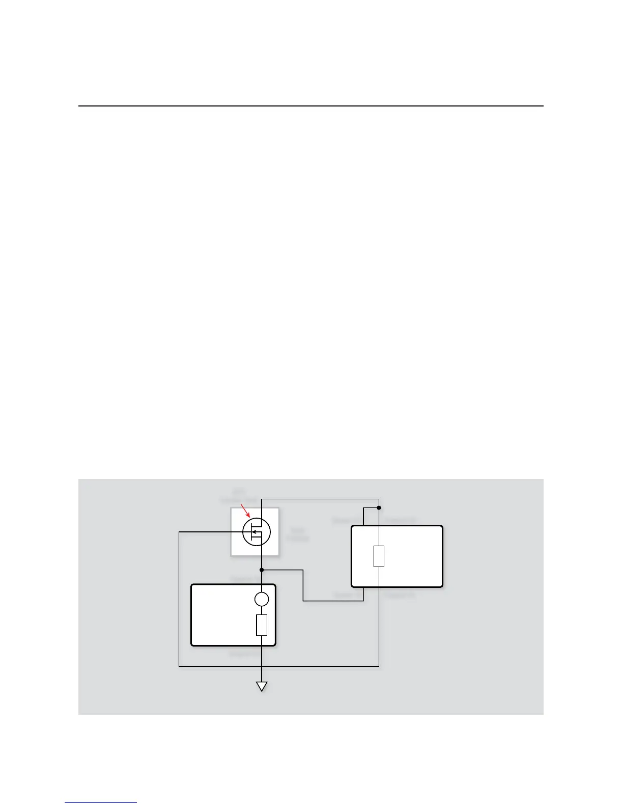
4.5.6 Example Program 11B: Self-bias
Threshold Voltage Tests
Use Program 11B to perform the self-bias threshold voltage test.
With the power off, connect a dual-channel System Source-1.
Meter instrument to the computer’s IEEE-488 interface.
Connect the test xture to both units using appropriate cables. 2.
Note that OUTPUT HI of SMUA is connected to the OUTPUT
LO of SMUB, while SENSE HI of SMUA is connected to the
OUTPUT HI of SMUB.
Turn on the instrument and allow the unit to warm up for two 3.
hours for rated accuracy.
Turn on the computer and start Test Script Builder (TSB). Once 4.
the program has started, open a session by connecting to the
instrument. For details on how to use TSB, see the
Series 2600
Reference Manual.
You can simply copy and paste the code from Appendix A in 5.
this guide into the TSB script editing window (Program 11B),
manually enter the code from the appendix, or import the TSP
file ‘FET_Thres_Fast.tsp’ after downloading it to your PC.
If your computer is currently connected to the Internet, you
can click on this link to begin downloading from http://www.
keithley.com/data?asset=50920.
Install an NPN FET such as a SD210 in the appropriate tran-6.
sistor socket of the test fixture.
Now, we must send the code to the instrument. The simplest 7.
method is to right-click in the open script window of TSB,
and select Run as TSP file. This will compile the code and
place it in the volatile run-time memory of the instrument.
To store the program in non-volatile memory, see the “TSP
Programming Fundamentals” section of the Series 2600 Refer-
ence Manual.
V
I
V
Series 2600
System
SourceMeter
Channel A
Sources V
DS
Series 2600
System
SourceMeter
Channel B
Sources I
D
(= I
S
)
Measures V
T
Test
Fixture
FET
Under Test
Output HI
Output LOSense LO
Sense HI
D
S
G
Output LO
Output HI
Figure 4-7. Configuration for self-bias threshold tests

Table of Contents

Question and Answer IconNeed help?

Do you have a question about the Keithley Series 2600 and is the answer not in the manual?

Keithley Series 2600 Specifications

General IconGeneral
ModelSeries 2600
Measurement FunctionsVoltage, Current, Resistance, Power
ResolutionUp to 6.5 digits
Current Source RangeUp to 10A
Communication InterfacesGPIB, USB
ApplicationsSemiconductor testing
CategorySource Measure Unit (SMU)
ChannelsSingle or Dual Channel (varies by model)

Summary

Section 1 General Information

1.1 Introduction

Discusses system configurations for application programs.

1.2 Hardware Configuration

Details system hardware configuration.

1.2.1 System Configuration

Describes the overall hardware configuration of a test system.

1.2.2 Remote/Local Sensing Considerations

Discusses sensing methods for optimizing accuracy.

1.3 Graphing

Explains how to visualize data using graphing.

Section 2 Two-terminal Device Tests

2.1 Introduction

Introduces tests for two-terminal devices.

2.2 Instrument Connections

Details instrument connections for two-terminal device tests.

2.3 Voltage Coefficient Tests of Resistors

Explains testing voltage coefficient of resistors.

2.4 Capacitor Leakage Test

Details testing capacitor leakage current.

2.5 Diode Characterization

Explains diode characterization tests.

Section 3 Bipolar Transistor Tests

3.1 Introduction

Introduces bipolar transistor tests.

3.2 Instrument Connections

Details instrument connections for bipolar transistor tests.

3.3 Common-Emitter Characteristics

Explains testing common-emitter characteristics for transistors.

3.4 Gummel Plot

Explains generating Gummel plots for transistors.

3.5 Current Gain

Discusses methods for measuring DC and AC current gain.

3.6 Transistor Leakage Current

Explains testing transistor leakage current.

Section 4 FET Tests

4.1 Introduction

Introduces FET testing.

4.2 Instrument Connections

Details instrument connections for FET tests.

4.3 Common-Source Characteristics

Explains common-source characteristics for FETs.

4.4 Transconductance Tests

Details transconductance testing for FETs.

4.5 Threshold Tests

Explains methods for determining FET threshold voltage.

Section 5 Using Substrate Bias

5.1 Introduction

Introduces substrate bias concepts.

5.2 Substrate Bias Instrument Connections

Details instrument connections for substrate bias.

5.3 Source-Measure Unit Substrate Biasing

Discusses SMU substrate biasing methods.

5.4 BJT Substrate Biasing

Explains substrate bias for BJTs.

Section 6 High Power Tests

6.1 Introduction

Introduces high power testing challenges.

6.1.1 Program 15 Test Configuration

Details test setup for high current tests.

6.1.2 Example Program 15: High Current Source and Voltage Measure

Shows high current sourcing with voltage measurement.

6.2 Instrument Connections

Details instrument connections for high power tests.

6.2.1 Program 16 Test Configuration

Details test setup for high voltage tests.

6.2.2 Example Program 16: High Voltage Source and Current Measure

Shows high voltage sourcing with current measurement.

Appendix A Scripts

Two-Terminal Device Scripts

Contains scripts for two-terminal device tests.

Bipolar Transistor Scripts

Contains scripts for bipolar transistor tests.

High Power Test Scripts

Contains scripts for high power tests.

FET Test Scripts

Contains scripts for FET tests.

Substrate Bias Scripts

Contains scripts for substrate bias tests.

Related product manuals