HYDRAULIC UNIT 9-3
196O903A
196O902A
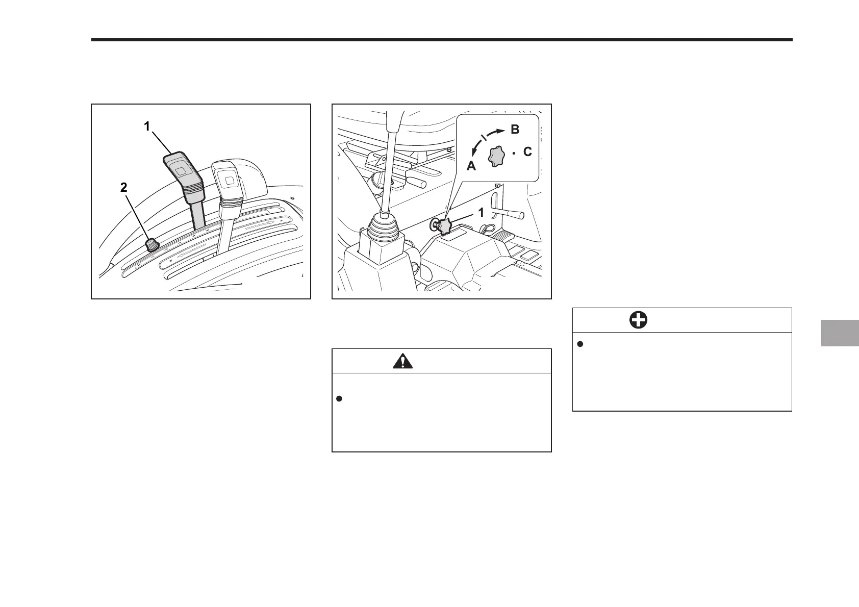
The lowering speed of the 3-point hitch
can be controlled by adjusting the 3-point
lowering speed knob.
(1) Hydraulic Control Lever
(2) Lock Bolt
(1) 3-Point Lowering Speed Knob
(A) FAST (C) LOCK
(B) SLOW
CAUTION
To avoid personal injury:
Fast lowering speed may cause
damage or injury. Lowering speed
of implement should be adjusted
to two or more seconds.
IMPLEMENT LOWERING LIMIT
The implement lowering limit can be
changed and adjusted by shifting the
locker.
LOWER LIMIT
The lower limit can be adjusted by mov-
ing the position of the locker. Shifting the
locker backward raises the lower limit
and shifting the locker forward lowers
the lower limit.
3-POINT HITCH LOWERING SPEED
IMPORTANT
To prevent overheating and dam-
age to the hydraulic system once
an implement is detached, be
sure the control screw is turned
back to the “Horizontal position”.
Hydraulic block type outlet is useful when
adding hydraulically operated equipment
such as:
front end loader, front blade, etc.
WHEN IMPLEMENT IS ATTACHED
1. Remove the plugs.
2. Route the implement inlet, outlet, and
return hoses as shown in the
illustration.
3. Move the control screw groove to
“vertical position” when implement is
attached.
HYDRAULIC BLOCK TYPE OUTLET
 Loading...