9-8 CK20
196O913A196O912A196O911A196O910A196O909A
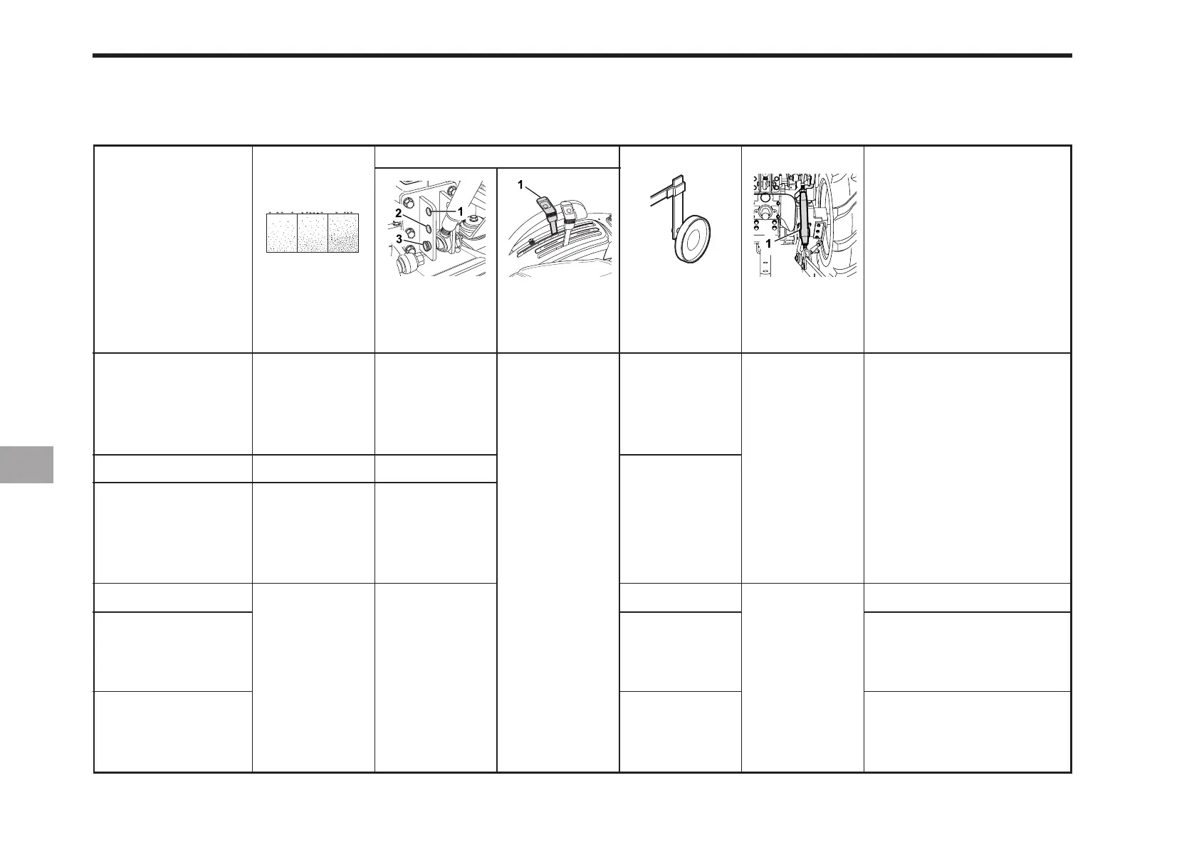
HYDRAULIC CONTROL UNIT USE REFERENCE CHART
In order to handle the hydraulics properly, the operator must be familiar with the following. Though this information may not be
applicable to all types of implements and soil conditions, it is useful for general conditions.
Moldboard plow
1 or 2
2 or 3
3
Position
control
YES/NO
Loose
Adjust the Turn buckle so
that the implement can
move 5 to 6 cm (2.0 to 2.4 in.)
laterally.
Turn buckle should be
tight enough to prevent
excessive implement
movement when imple-
ment is in raised position.
with draft control
Implement
Soil
condition
Top link
mounting holes
Position
control lever Gauge wheel
Remarks
Webber, rider…
Tighten
With implements with
gauge wheels, lower the
position control lever all
the way.
Disc plow
2 or 3
Harrow
(spike, spring
tooth, disc type)
Earthmover, Digger,
scraper, manure
fork, rear carrier….
Mower (mid-and
rear-mount type
Hayrake,tedder….
YES/NO
-
2 or 3
-
-
Turn buckle
Light soil
Medium soil
Heavy soil
-
-
-
--
-
 Loading...