11 TUNING THE CHASSIS 35
11.12 Adjusting the compression damping of the fork
Info
The hydraulic compression damping determines the fork suspension behavior.
B01033-10
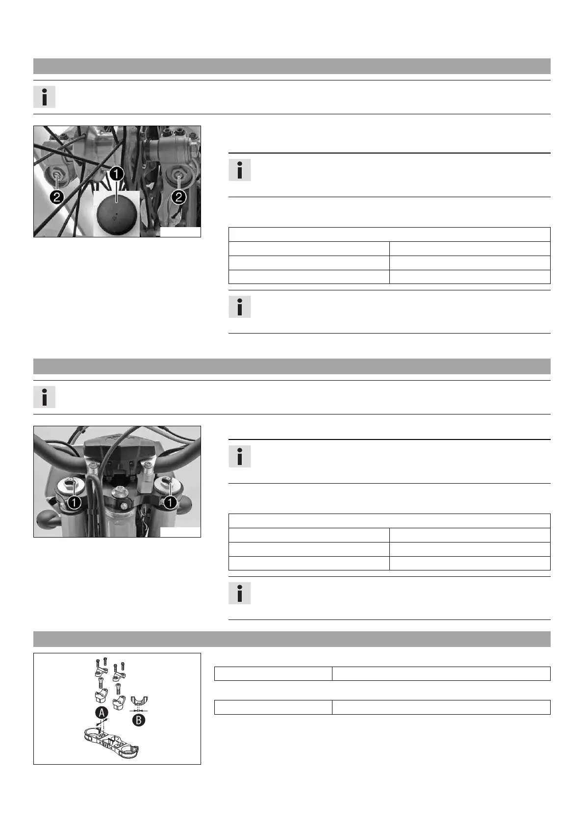
– Remove protection caps 1.
– Turn adjusting screws 2 clockwise all the way.
Info
Adjusting screws 2 are located at the bottom end of the fork legs.
Make the same adjustment on both fork legs.
– Turn counterclockwise by the number of clicks corresponding to the fork type.
Guideline
Compression damping
Comfort 25 clicks
Standard 20 clicks
Sport 15 clicks
Info
Turn clockwise to increase damping; turn counterclockwise to reduce damp-
ing.
– Mount protection caps 1.
11.13 Adjusting the rebound damping of the fork
Info
The hydraulic rebound damping determines the fork suspension behavior.
B01728-10
– Turn adjusting screws 1 clockwise all the way.
Info
Adjusting screws 1 are located at the top end of the fork legs.
Make the same adjustment on both fork legs.
– Turn counterclockwise by the number of clicks corresponding to the fork type.
Guideline
Rebound damping
Comfort 25 clicks
Standard 20 clicks
Sport 15 clicks
Info
Turn clockwise to increase damping; turn counterclockwise to reduce damp-
ing.
11.14 Handlebar position
B01035-10
On the upper triple clamp, there are two holes at a distance of A to each other.
Hole distance A 15 mm (0.59 in)
The holes on the handlebar supports are placed at a distance of B from the center.
Hole distance B 3.5 mm (0.138 in)
The handlebar supports can be mounted in four different positions.
 Loading...