KiSC issued 09, 2007 A
The
l
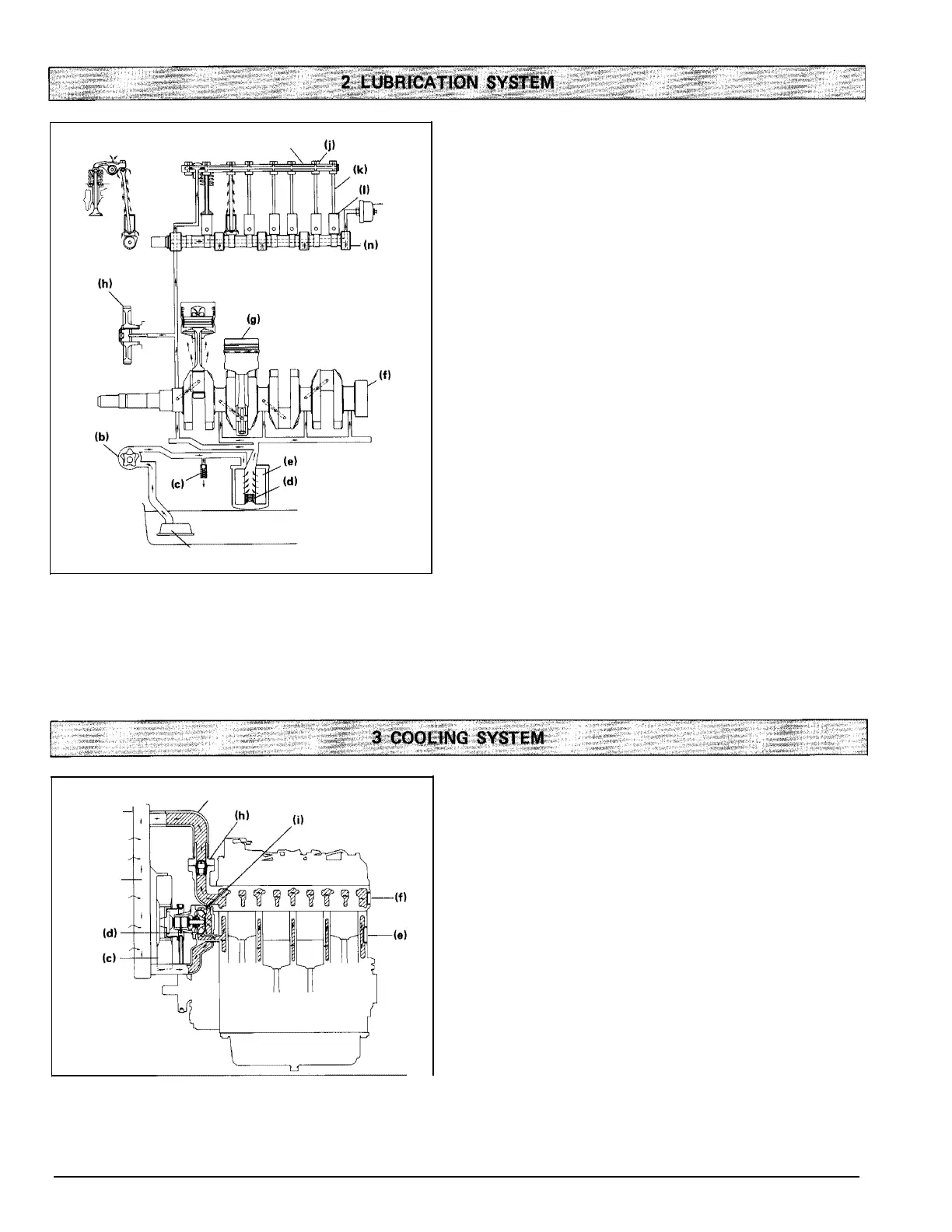
u brication system consists of a trochoide rotor-type
driven oil pu mp, oil filter cartridge, oil pressure regulati ng
valve, oil switch a nd oi
l
filter.
Oil is sucked by the oil pu mp (b) from the oi
l
pa n (o) through
the oil f ilter (a) , a nd the oi
l
is kept at 294 to 441 kPa (3.0 to
4.5 kgf/cm
2
,
42 to 64 psi) by a n oil pressure regulati ng va lve
(c)
i
nstalled
i
n the gear case. Then oi
l
flows towards the f
i
lter
ca rtridge where it wil
l
be f u rther f
i
ltered
-
To ensure the
suppl y ing of
l
u bricated oil, a by-pass valve (d) is prov ided,
the va lve opens when the f
i
lter element (e) is restr icted
-.
From the f ilter cartridge, the pressured oil is then d istributed
i
nto two parts: one pa rt wil
l
be f ed through cra nkshaf
t
passage to the crank pi n bea ri ng a nd the other to the rocker
arm shaf
t
(
i) th rough the frame. Oi
l
then returns to oil pa n
by force of gravity.
A
n
oil pressure switch
(
m) is provided on the way for watch-
i
ng the oil pressure drop. The oil pressure switch can be con-
nected to the termi nals of the warni ng lamp on the hour-
meter
u
nit (optional part), the
l
ight wil
l
be
l
ight for warni ng
the operator
if
the oi
l
pressure drops below 50 kPa (0.5
kgf /cm
2
,
7 .1 psi) .
If the warn
i
ng la mp rema ins
l
ight wh
i
le engine is at normal
operation, stop the engine im med iately a nd check the oil
pressure.
(a)
Oil filter
(b)
Oil pump
(c)
Pressure regulating valve
(d)
By-pass valve
(e)
Filter element
(f)
Crankshaft
(g)
Piston
(h)
Idle gear
(i)
Rocker arm shaft
(j)
Rocker-arm
{k)
Push rod
(I)
Tappet
(m)
Oil pressure switch
(n)
Camshaft
(o)
Oil pan
The cool
i
ng system consists of a rad iator (optional part),
centrif uga
l
water pu mp, suction fa n and thermostat.
The water flow is cooled th rough the rad iator core
(
b) a nd
the fa n (c) set beh
i
nd the rad iator (a) pul ls cool
i
ng air
through the core to
i
mprove cool
i
ng.
The pump (d) sucks the cooled water, forces it
i
nto the
cy
l i
nder block (e) and draws out the hot water. Then the
cool
i
ng is repeated. F urthermore, to control tem perature of
water, a thermostat
(
h) is provided on the way. When the
thermostat opens, t he water moves d
i
rectl y to rad iator, but
when it closes, the water moves toward the water pum p
th rough the by-pass
( i )
between thermostat and water pu mp.
The opening temperature of thermostat is about 82°C
(176.3°F).
(a)
Radiator
(f) Cylinder head
(b)
Radiator core (g) Water pipe
(c)
Suction fan (h) Thermostat
(d)
Water pump (i) By-pass
(e)
Cyl
i
nder
block
18
A
Lubrication S
stem
i
Im
o
A
Coolin
S
stem
a
b
0073F018
0073F01
a
 Loading...