KiSC issued 09, 2007 A
(A) Valve clearance
Timing window
8
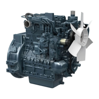
Adjusting Valve Clearance
1)
Remove the cylinder head cover.
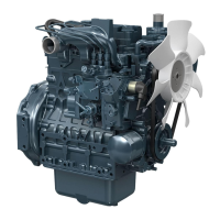
2)
Turn the flywheel and align the 1TC or 1- 4TC mark
with the projection in the window on the flywheel
housing to position the 1st cylinder at the top dead
center during comPfession.
3)
Measure the clearance at the valves marked with in
the table below with a feeler gauge.
4)
If the clearance is not within the factory specifications,
turn the adjusting screw to adjust.
5)
Turn the flywheel just one turn to position the 1st
cylinder at the top dead center during overlap.
6)
Measure the clearance at the valves marked with
•
in
the table below with a feeler gauge.
7)
If the clearance is not within the factory specifications,
turn the adjusting screw to adjust.
(Note)
•
Engine must be cool.
C
019 F026
A069F003
[V1502-B, V1702-B, V1902-Bl
•
•
41.l
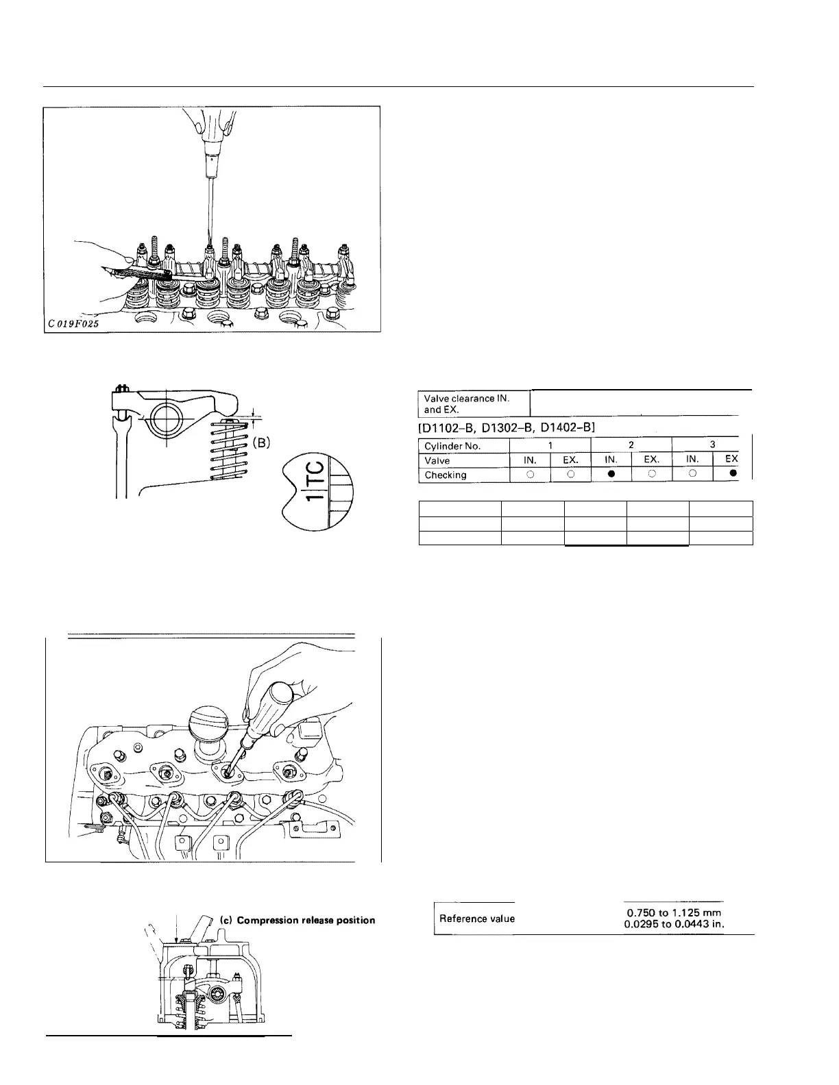
Adjustment of Compression Release
1) Close the exhaust val ve completel y.
2)
Remove the decompression adjust cover from the head
cover.
3)
Pu
l l
the decompression lever.
4)
Reduce the valve clearance to zero by means of the
decom pression adjust bol t. Gain access to the adju t
bol t th rough the wi ndqw. Then, screw
i
n the bol t by
1
to
1.5
tu rns and tighten the lock nu t.
(A)
Compression release adjustment
(a)
Compression release window cover
( Note)
•
Af ter adjustment, turn the crankshaf t by hand and check
to see that
the valve and the piston should not be i n
contact with each other because the depression clearance
is too small.
54
(b) Compression
position
i
.:'.f'F;.Z:-=j'
=
:'.:::::::,.-lnj
I
(d) 0.750
to
1.125mm
0.0295
to
0.0443
in.
C
019 F028
\
C Ol 9 F02
Factory
s
ec.
0.18 to 0.22 mm
0.0071 to 0.0087 in.
Cylinder No.
1
2
3
4
Valve
IN.
EX.
IN.
EX.
IN.
EX.
IN.
EX.
Checking
0
0
I
•
•
I
0
I
 Loading...