C019 F055
COJ 9
05
0
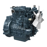
Checking Side Clearance of R ing in Groove
1)
Remove the piston ri ng from the piston.
2)
Place the ri ng
i
n its groove as is shown at lef t, and measu re
the cleara nce.
3)
I
f the measu rement is not wi th
i
n the reference val ue,
replace the ri ng.
( Note)
•
As the top ring is a keyston type, it cannot be measured
by this method.
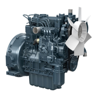
()
Checking Connecting Rod Alignment
1)
Remove the connecti ng rod crank pi n metal and tighten
the rod bol t.
2)
Attach the connecti ng rod to the con necti ng rod al igner.
3)
Place the ga uge on the piston pi n.
Measu re the ga p between the pi n of the gauge and the f lat
su rface of the a
Iigner.
4)
If the measurement exceeds the a
l
lowa bl e
l i
m it, replace
the rod.
( I m portant)
•
Because the inside diameter· of the connecting rod small-
end bushing is used as the basis, check carefully
if
it
is
worn or not.
--t
0
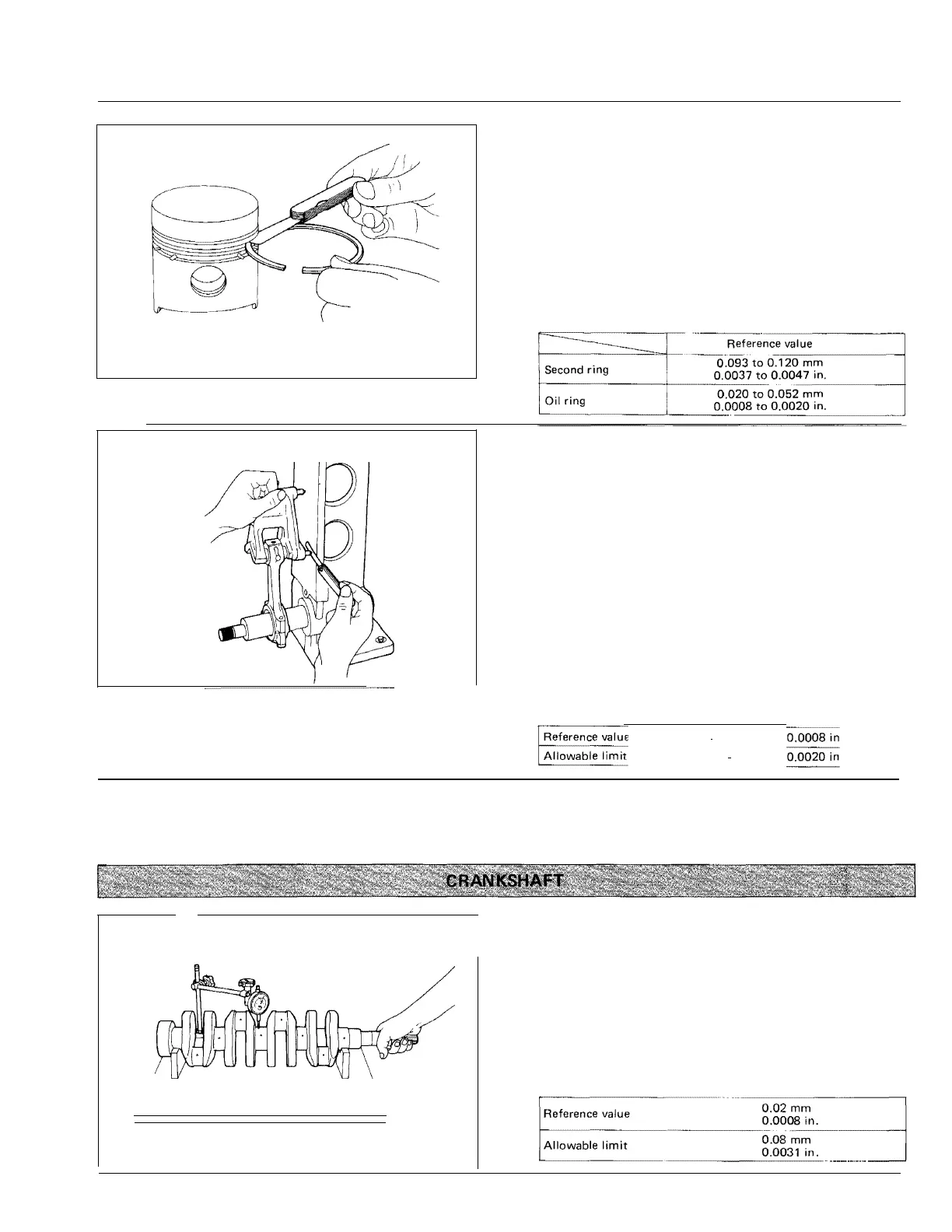
Checking Crankshaft Alignment
1)
Place V-blocks on a su rface plate, and put either end of
the jou rnal on them.
2)
Set a d ial gauge on the center journal .
3)
R ead the d ia
l
ga uge wh
i
le rotati ng the cra nkshaf t slowly.
Cra n kshaf t flexure is
i
nd icated by ha lf of the read
i
ng.
4)
If the read
i
ng exceeds the al lowa ble
l i
mit, replace the
era nkshaf t.
63
KiSC issued 09, 2007 A
C019 F05
0.02
mm
··
0.05
mm
 Loading...