KiSC issued 09, 2007 A
(A)
Governo
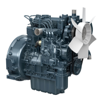
4-5 GOVERNOR
The engi ne f eatu res K u bota's excl usive ba
l
l-ty pe va ria bl e
speed governor a nd a torq ue spr
i
ng is prov ided to
i
m prove
engi ne torq ue performa nce a nd to prevent engi ne from stal l-
i
ng
i
n case of overload.
How
it
works:
0073F020
When the speed control
l
ever is set at its ma x
i
mu m posit ion,
the governor spr
i
ng
(
b) pul
Is
the control rack towa rd the
maxi mu m quantity th rough fork
l
evers 1 and 2 (e,
f
). But as
the engine speed
i
ncreases, the governor bal ls (d
)
on the ca m-
shaf t, by its centrif uga
l
force, move outwa rd a nd push bac
the fork lever 1 a nd 2 th rough the governor sleeve
(
g) . The
control rack position wil
l
e decided when the force created
by governor ba
l l
s eq ual s the cou nterforce of the governor
s
ri n
.
4-4
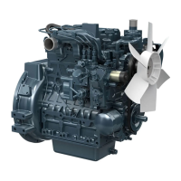
INJECTION NOZZLE
The nozzle is a throttl e-type one, it f eatures
l
ow f uel con-
sum ption a nd works wel
l
with K u bota's spherica
l
combus-
tion chamber.
The nozzle valve open
i
ng pressu re is abou t 13.7 to 14.7 MPa
(140 to 150 kgf /cm
2
,
1990 to 2130 psi) , the pressu re over-
comes the cou nterforce of nozzl e val ve spri ng
(
b) , and push
the val ve
(
e) u p
i
nsta ntl y, the f uel is then
i
njected
i
n a pro-
per qua ntity
i
nto the swirl
i
ng a
i
r
i
n the combustion cha mber
(f
)
for combustion. Add ition or red uction of sh
i
m ca n adjust
the openi ng pressure. A sh
i
m of 0.1 m m corresponds to
980 kPa
(
1O kgf /cm
2
,
142 psi) cha nge
i
n open
i
ng pressu re.
(a)
Adjusting Washer
(b)
Nozzle Spring
(c)
Push Rod
(dl
Nozzle Nut
(el
Needle Valve
(f)
Combustion Chamber
(gl
Fuel Overflow Nipple
(h) Fuel Overflow pipe
(a)
Injection pump
(bl
Goernor spring
(c)
Torque spring
(d)
Governor balls
(e)
Fork lever 2
(f)
Fork lever 1
(g)
Governor sleeve
As the engi ne speed d ecreases, the centrif uga
l
force d
i
m
i
n
i-
shes a nd the ba
l
ls move
i
nwa rd. As a resu
l
t, the governor
spr
i
ng tension pu
l l
s the control rack for
i
ncreasi ng the
f
uel.
Due to the ba la nce between spring tension a nd centr
if
uga
l
force of governor ba
l
ls, a near
l
y constant engi ne speed is
obta
i
ned.
22
Al
In
ection Nozzle
f
0011F046
 Loading...