M.5
FUEL
SYSTEM
92.4mm STROKE SERIES
WSM,
01092
FUEL
SYSTEM
[I]
GENERAL
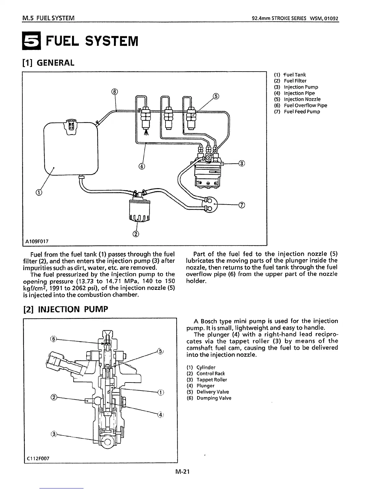
(1)
fuelTank
(2) Fuel Filter
(3)
Injection Pump
(4) Injection Pipe
(5)
Injection Nozzle
(6)
Fuel Overflow Pipe
(7)
Fuel Feed Pump
A109F017
Fuel from the fuel tank
(1)
passes through
the
fuel
filter
(2),
and
then
enters
the
injection pump
(3)
after
impurities such
as
dirt, water,
etc.
are removed.
The fuel pressurized
by
the
injection pump to
the
opening pressure
(13.73
to
14.71
MPa,
140
to
150
kgfkm2,
1991
to
2062
psi), of the injection nozzle
(5)
is
injected into the combustion chamber.
Part
of
the
fuel fed to the injection nozzle
(5)
lubricates the moving parts
of
the
plunger inside the
nozzle, then returns to
the
fuel tank through
the
fuel
overflow pipe
(6)
from the upper part
of
the
nozzle
holder.
[2]
INJECTION
PUMP
C112F007
M-2
I
A
Bosch type mini pump
is
used for the injection
pump.
It
is
small, lightweight and easy to handle.
The plunger
(4) with
a
right-hand lead recipro-
cates
via
the tappet roller
(3)
by means of the
camshaft fuel cam, causing
the
fuel to be delivered
into
the
injection nozzle.
(1) Cylinder
(2) Control Rack
(3)
Tappet Roller
(4) Plunger
(5)
Delivery Valve
(6)
Dumping Valve
 Loading...