5.1
ENGINE
BODY
92.4mm
STROKE
SERIES
WSM,
01092
Connecting rod
alignment
I
ST10F040
I'
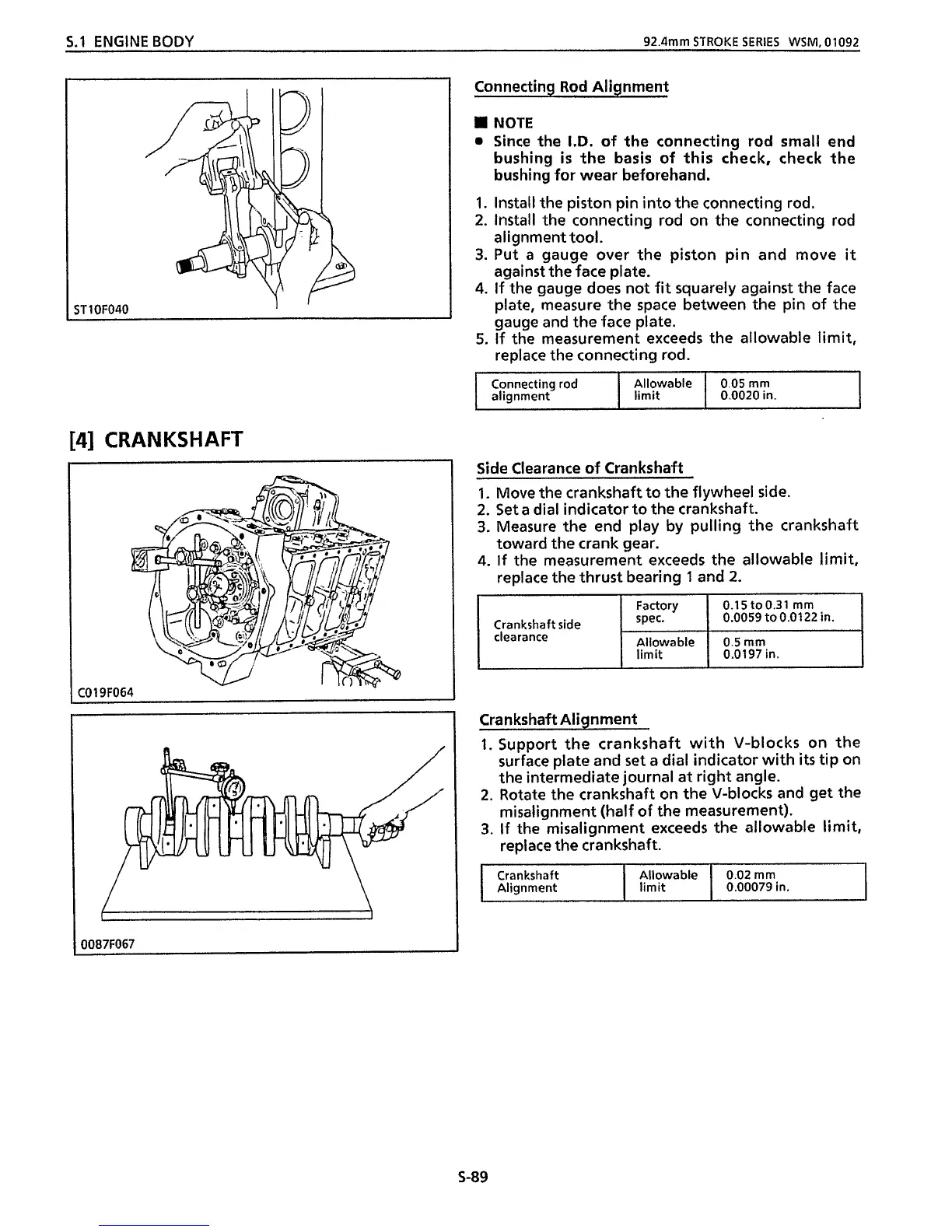
Allowable 0.05 mm
limit
0.0020
in.
Connecting Rod Alignment
Factory
spec.
Allowable
limit
Crankshaft side
clearance
I
NOTE
0
Since the
I.D.
of the connecting rod small end
bushing
is
the basis
of
this check, check the
bushing for wear beforehand.
1.
Install the piston pin into the connecting rod.
2.
Install the connecting rod on the connecting rod
alignment tool.
3.
Put
a
gauge over the piston pin and move
it
against the face plate.
4.
If the gauge does not fit squarely against the face
plate, measure the space between the pin of the
gauge and the face plate.
5.
If the measurement exceeds the allowable limit,
replace the connecting rod.
0.15t00.31
mm
0.0059to0.0122 in.
0.5
rnrn
0.0197 in.
Crankshaft
Alignment
[4]
CRANKSHAFT
Allowable
0.02
mm
limit
0.00079
in.
I
C019F064
I
/"
"\
I
I
0087F067
Side Clearance
of
Crankshaft
S-89
 Loading...