M.5
FUEL
SYSTEM
92.4mm
STROKE SERIES
WSM,
01092
(I)
Pump Element
C047F028
(2)
Delivery Valve
I
001
1
F042
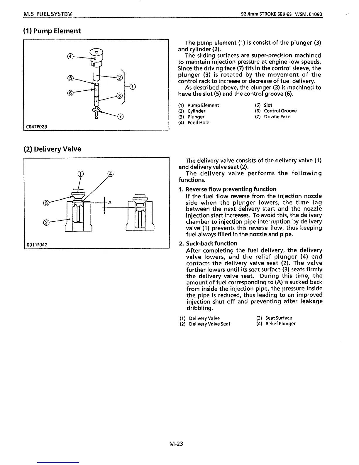
The pump element
(1)
is
consist
of
the plunger
(3)
and cylinder
(2).
The sliding surfaces are super-precision machined
to maintain injection pressure at engine low speeds.
Since
the
driving face
(7)
fits
in
the
control sleeve,
the
plunger
(3)
is
rotated by the movement of the
control rack
to
increase or decrease
of
fuel delivery.
As
described above, the plunger
(3)
is
machined to
have the slot
(5)
and
the
control groove
(6).
(1)
Pump Element
(5)
Slot
(2)
Cylinder
(6)
Control Groove
(3)
Plunger
(7)
Driving Face
(4)
FeedHole
The delivery valve consists of the delivery valve
(1)
The delivery valve performs the following
and delivery valve seat
(2).
functions.
1.
Reverse flow preventing function
If
the fuel flow reverse from the injection nozzle
side when the plunger lowers, the time lag
between
the
next delivery start and the nozzle
injection start increases. To avoid
this,
the delivery
chamber to injection pipe interruption by delivery
valve
(1)
prevents
this
reverse flow, thus keeping
fuel always filled
in
the nozzle and pipe.
After completing
the
fuel delivery, the delivery
valve lowers, and
the
relief plunger
(4)
end
contacts the delivery valve seat
(2).
The valve
further lowers until
its
seat surface
(3)
seats firmly
the delivery valve seat. During
this
time, the
amount
of
fuel corresponding to (A)
is
sucked back
from inside
the
injection pipe,
the
pressure inside
the pipe
is
reduced, thus leading to an improved
injection shut off and preventing after leakage
dribbling.
2.
Suck-back
function
(1)
Delivery Valve
(3)
Seat Surface
(2)
Delivery Valve Seat
(4)
Relief Plunger
M-23
 Loading...