S.G
GENERAL
92.4mm
STROKE
SERIES
WSM,0109A
kgfom
0.7 to 0.9
9.5
to 10.0
4.7
to 5.2
7.0
to 7.5
10.0to
11.0
3.7
to 4.2
4.5
to 5.0
2.4 to 2.8
2.4
to 2.8
14.0to 16.0
32.0
to
34.0
2.0
to 2.5
5.0 to 7.0
1.5
to 2.0
2.5
to 3.5
[3J
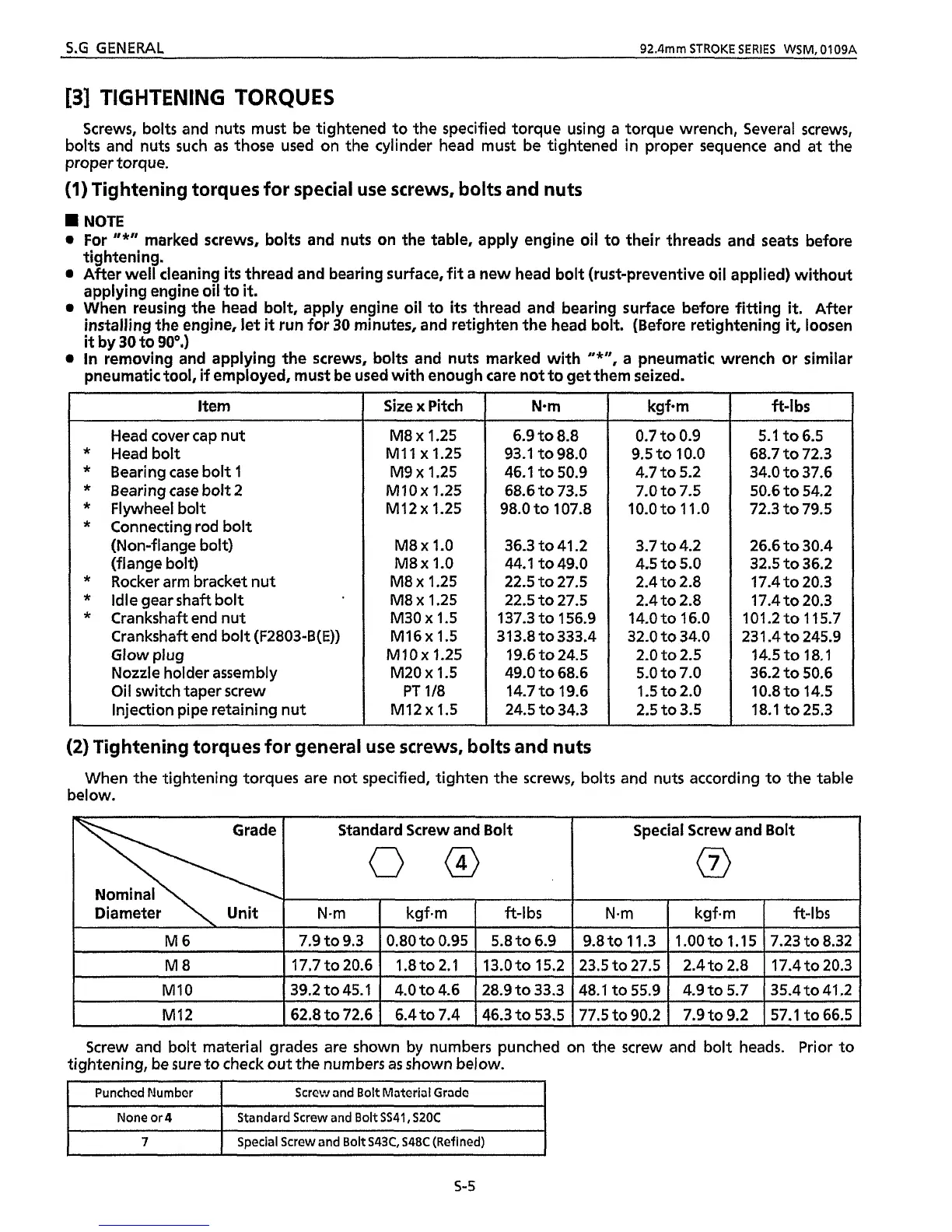
TIGHTENING TORQUES
ft-I
bs
5.1 to6.5
68.7
to 72.3
34.0
to 37.6
50.6
to 54.2
72.3 to 79.5
26.6
to 30.4
32.5
to
36.2
17.4 to 20.3
17.4
to 20.3
101.2to 115.7
231.4
to 245.9
14.5
to
18.1
36.2 to 50.6
10.8to
14.5
18.1
to 25.3
Screws, bolts and nuts must be tightened to the specified torque using
a
torque wrench, Several screws,
bolts and nuts such
as
those used on the cylinder head must be tightened in proper sequence and
at
the
proper torque.
(1)
Tightening torques for special use screws, bolts and nuts
NOTE
0
For
"*"
marked screws, bolts and nuts on the table, apply engine oil to their threads and
seats
before
tightening.
0
After
well
cleaning
its
thread and bearing surface,
fit
a
new head bolt (rust-preventive oil applied) without
applying engine oil to
it.
0
When reusing the head bolt, apply engine oil to
its
thread and bearing surface before fitting
it.
After
installing the engine,
let
it
run
for
30
minutes, and retighten
the
head bolt. (Before retightening
it,
loosen
it
by
30
to
90°.)
0
in removing and applying the screws, bolts and nuts marked with
"*",
a
pneumatic wrench or similar
pneumatic tool,
if
employed, must be used with enough care not to get them seized.
Unit
N-m
Item
Head cover cap nut
*
Headbolt
*
Bearing
case
bolt 1
*
Bearing case bolt 2
*
Flywheel bolt
*
Connecting rod bolt
(Non-flange bolt)
(flange bolt)
*
Rocker arm bracket nut
*
idle gear shaft bolt
*
Crankshaft end nut
Crankshaft end bolt
(F2803-B(E))
Glow
plug
Nozzle holder assembly
Oil switch taper screw
Injection pipe retaining nut
kgf.m
ft-l
bs
Size
x
Pitch
N-m
9.8 to
1
1.3
M8 x 1.25
M11 x 1.25
M9
x
1.25
MlOx 1.25
M12x 1.25
M8 x
1.0
M8x
1.0
M8 x 1.25
M8 x 1.25
M30
x
1.5
M16x 1.5
MlOx 1.25
M20 x 1.5
PT
118
M12 x 1.5
kgf-m
ft-I
bs
1
.OO
to 1.15 7.23 to 8.32
Nom
6.9 to
8.8
93.1 to 98.0
46.1
to 50.9
68.6
to 73.5
98.0
to 107.8
36.3
to 41.2
44.1
to 49.0
22.5
to
27.5
22.5
to 27.5
137.3
to 156.9
313.8 to333.4
19.6
to 24.5
49.0
to 68.6
14.7
to 19.6
24.5
to 34.3
M6
M8
7.9 to 9.3
0.80
to 0.95 5.8 to 6.9
17.7
to 20.6 1.8 to 2.1 13.0
to
15.2
(2)
Tightening torques
for
general use screws,
bolts
and nuts
below.
When the tightening torques
are
not specified, tighten the screws, bolts and nuts according to the table
48.1
to 55.9
77.5
to 90.2
\
Grade
I
Standard Screw and Bolt
4.9
io
5.7 35;Go 41.2
7.9
to 9.2 57.1 to 66.5
I\\
I
None or4
7
00
Standard Screw and Bolt
SS41, S20C
Special Screw and Bolt
S43C, S48C
(Refined)
~
MI0
I
39.2 to 45.1
I
4.0 to 4.6
I
28.9 to 33.3
I
M12
I
62.8 to 72.6
I
6.4 to 7.4
I
46.3 to 53.5
Special Screw and Bolt
(7)
23.5 to 27.5
I
2.4 to 2.8
I
17.4 to 20.3
I
Screw and bolt material grades are shown by numbers punched on the screw and bolt heads. Prior to
tightening, be sure to check out
the
numbers
as
shown below.
Punchcd Number
1
Scrcvr and Bolt Material Gradc
I
5-5
 Loading...