6-S10
G2160, WSM
HYDRAULIC SYSTEM
[3] MOWER LIFT LINKAGE
(1) Checking and Adjusting
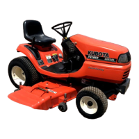
Clearance between Rear Link and Frame Stopper
1. Lift the rear link assembly (1) to the highest position.
2. Measure the clearance (L) between the rear link assembly and
frame stopper (2).
3. If the measure is not within the factory specifications, adjust the
length (L1) of upper lift link (4) and lower lift link (3).
(Reference)
• L1 :350mm (13.8in.)
W1018142
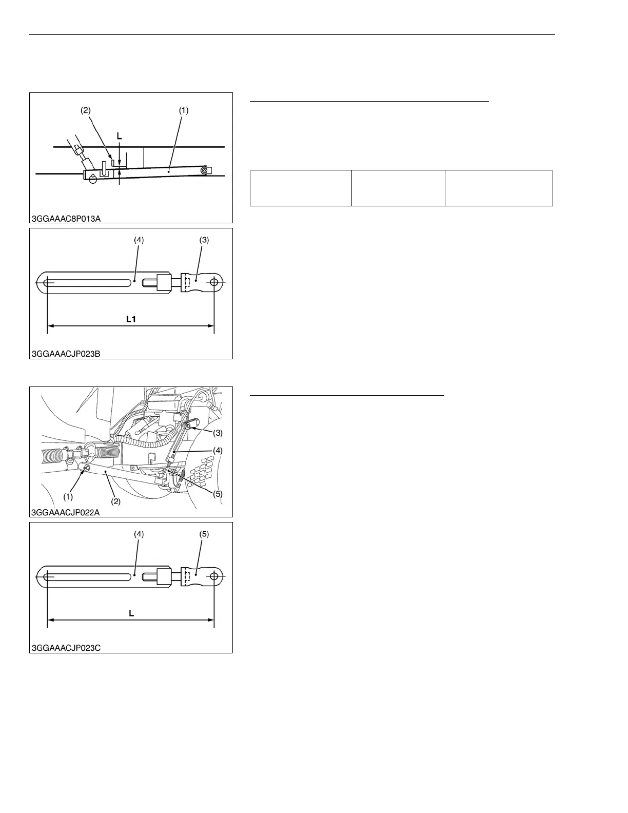
(2) Disassembling and Assembling
Upper Lift Link and Rear Link Assembly
1. Pull out the rue ring cotters (3) and plane washers.
2. Remove the upper lift links (4).
3. Pull out the cotter pin (1) and plane washer.
4. Remove the L.H. rear link assembly (2).
5. Remove the R.H. rear link assembly retaining lock nut and bolt.
6. Remove the R.H. rear link assembly.
(When reassembling)
• Apply the grease to the rotary sliding surface.
• Adjust the upper lift link and lower lift link referring to the
"MOWER" section.
• Tighten the R.H. rear link assembly lock nut and bolt, leaving
gap between the frame and the lock nut as little as possible.
Also be sure that the rear link assembly turns smoothly.
(Reference)
• L : 350mm (13.8 in.)
W1018593
Clearance (L) between
rear link and frame
stopper
Factory spec.
1.0 to 2.0 mm
0.04 to 0.08 in.
(1) Rear Link Assembly
(2) Frame Stopper
(3) Lower Lift Link
(4) Upper Lift Link
(1) Cotter Pin
(2) L.H. Rear Link Assembly
(3) Rue Ring Cotter
(4) Upper Lift Link
(5) Lower Lift Link
 Loading...