8-S28
G2160, WSM
ELECTRICAL SYSTEM
(6) PTO Switch
PTO Switch
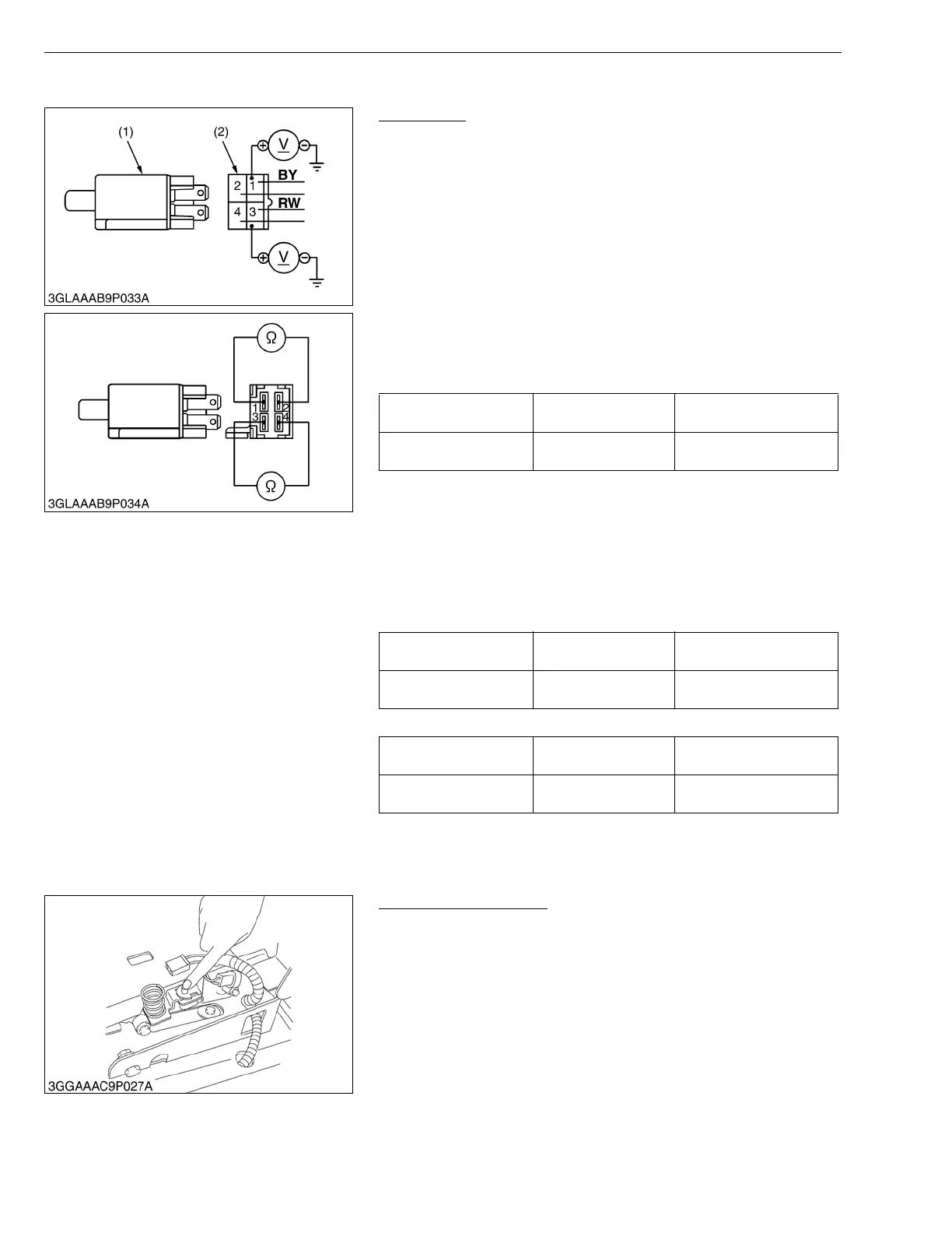
1) Connector Voltage
1. Turn the main switch off.
2. Disconnect the 4P connector from the PTO switch (1).
3. Turn the main switch to “ON” position.
4. Measure the voltage with a voltmeter across the connector 3
terminal and chassis.
5. If the voltage differs from battery voltage, the wiring harness is
faulty.
6. Turn the main switch to “START” position.
7. Measure the voltage with a voltmeter across the connector 1
terminal and chassis.
If the voltage differs from battery voltage, the wiring harness is
faulty.
2) Terminal Continuity
1. Measure the resistance with an ohmmeter between the terminals
when the PTO clutch lever is set at “DISENGAGE” position.
2. Measure the resistance with an ohmmeter between the terminal
when the PTO clutch lever is set at “ENGAGE” position.
3. If the resistance values specified below are not indicated, the
PTO switch is faulty.
■ PTO clutch lever is set at “DISENGAGE” position.
■ PTO clutch lever is set at “ENGAGF” position.
W1029375
(7) Seat Switch
Seat Switch Continuity
1. Disconnect the 2P connector for the seat switch.
2. Using an ohmmeter, check for continuity between the connector
terminals.
There should be continuity when the seat switch is depressed
(seated) and no continuity when the seat switch is released
(standing).
W1030037
Voltage
(1 terminal - Chassis)
Factory spec. Battery voltage
Voltage
(3 terminal - Chassis)
Factory spec. Battery voltage
Resistance
(1 terminal-2 terminal)
Factory spec. Continuity
Resistance
(3 terminal-4 terminal)
Factory spec. Continuity
Resistance
(1 terminal-2 terminal)
Factory spec. Infinity
Resistance
(3 terminal-4 terminal)
Factory spec. Infinity
(1) PTO Switch (2) 4P Connector
 Loading...