6-M2
G2160, WSM
HYDRAULIC SYSTEM
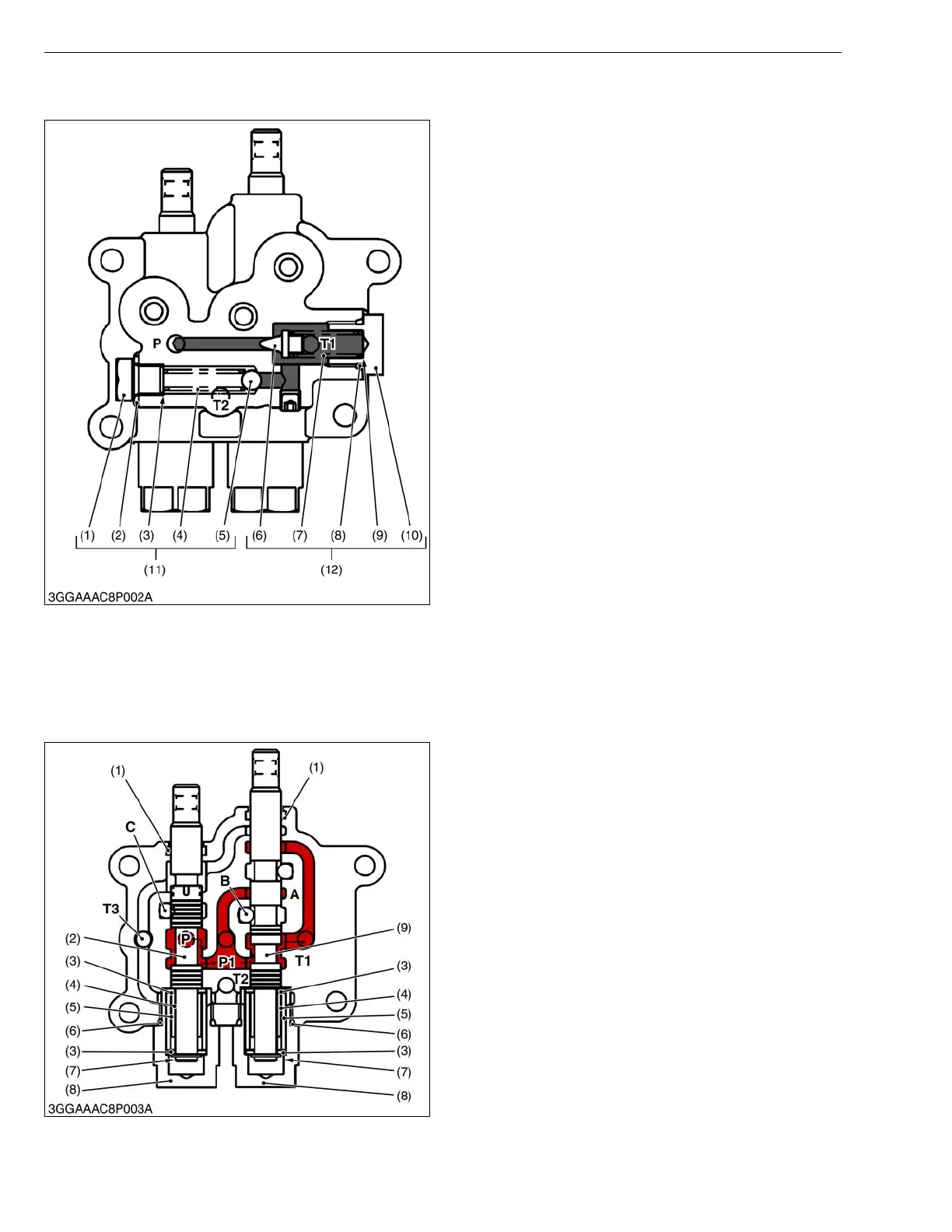
2. RELIEF VALVE
This machine is equipped with two direct-acting relief
valves (11), (12).
The main relief valve (12) serves to control the
pressures of the mower lift cylinder and grass collector
cylinder and to protect the entire hydraulic system
against damage.
The filter relief valve (11) is used to protect the entire
hydraulic system from an excessive pressure that would
be caused by a clogged oil filter.
These relief valves consist of poppet valve, spring,
shims and plug.
When the oil pressure in the circuit is lower than the
setting pressure of the relief valve, the poppet is closed
by the spring.
When the oil pressure rises above the valve setting
pressure and overcomes the spring force, the valve
opens. The oil then flows out to the transmission case,
preventing any further rise in pressure. The relief valve
closes again when enough oil is released to drop
pressure below the valve setting pressure.
W1012822
3. CONTROL VALVE
In this hydraulic system, the mower lifting circuit is given priority to the grass collector dumping circuit.
[1] MOWER LIFTING CIRCUIT
Suppose that the grass collector dumping spool
(spool 2) (9) is in the neutral position.
■ Neutral
The oil coming from port P flows to the port T1.
The oil then flows through the oil filter and back to the
hydrostatic transmission (HST).
The port C, which is connected with the mower lift
cylinder, stays closed by the spool 1 (for mower cylinder)
(1). In this way, the mower is held at a certain level.
W1013046
(1) Bolt
(2) Washer with Rubber
(3) Shims
(4) Spring
(5) Steal Ball
(6) Poppet
(7) Spring
(8) O-ring
(9) Shims
(10) Plug
(11) Filter Relief Valve
(12) Main Relief Valve
P : Pump Port
T1, T2: Tank Port
(1) Seat
(2) Spool 1
(for Mower Cylinder)
(3) Plain Washer
(4) Collar
(5) Return Spring
(6) O-ring
(7) Snap Ring
(8) Plug
(9) Spool 2
(for Grass Collector Cylinder)
A : Grass Collector Cylinder
Port
B : Grass Collector Cylinder
Port
C : Mower Lift Cylinder Port
P : Pump Port
T1, T2 : Tank Port
P1, T3 : These ports are
blocked the control
valve adaptor. These
ports are designed to
activate the relief
valves. Actually no oil
flows in and out of
these ports.
 Loading...