8-S31
G2160, WSM
ELECTRICAL SYSTEM
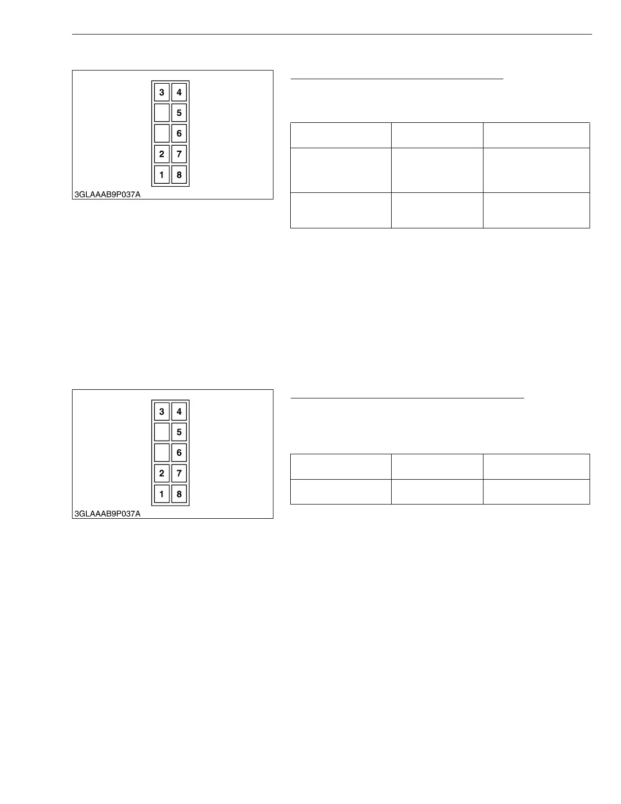
(2) KRA system Unit (Harness connector side)
KRA system Unit Connector Battery Voltage
1. Turn the main switch to “ON” position. But do not start the
engine.
2. Measure voltage with a voltmeter.
3. If 3 terminal - 8 terminal voltage is not battery voltage check the
KRA system fuse blown and wire harness disconnected.
4. If 5 terminal - 8 terminal, 6 terminal - 8 terminal voltage are not
battery voltage, check wire harness disconnected.
5. Continuity is not 0 Ω, harness or KRA system switch is defective.
6. If KRA system fuse is not blown and wire harness is connected,
the KRA system unit is defective, and replace the KRA system
unit as an unit.
W1030717
KRA system Unit Connector Terminal Continuity
1. Measure the resistance with an ohmmeter when the main switch
is “OFF” position.
2. Push on the KRA system switch on panel board, and measure
the resistance between 1 terminal and 2 terminal.
W1031477
Voltage
(3 terminal- 8 terminal)
Factory spec. Battery Voltage
Voltage
(5 terminal- 8 terminal)
HST pedal “Neutral” or
“Forward”
Factory spec. Battery Voltage
Voltage
(6 terminal- 8 terminal)
PTO lever “Disengage”
Factory spec. Battery Voltage
(1) KRA System Switch
(2) KRA System Switch
(3) Fuse
(4) Start Switch
(5) Reverse Switch
(6) PTO Switch
(7) Lamp
(8) GND.
Resistance-
(1 Terminal - 2 Terminal)
Factory spec. 0 Ω
Resistance-
(8 Terminal - Chassis)
Factory spec. 0 Ω
 Loading...