G-43
G2160, WSM
G GENERAL
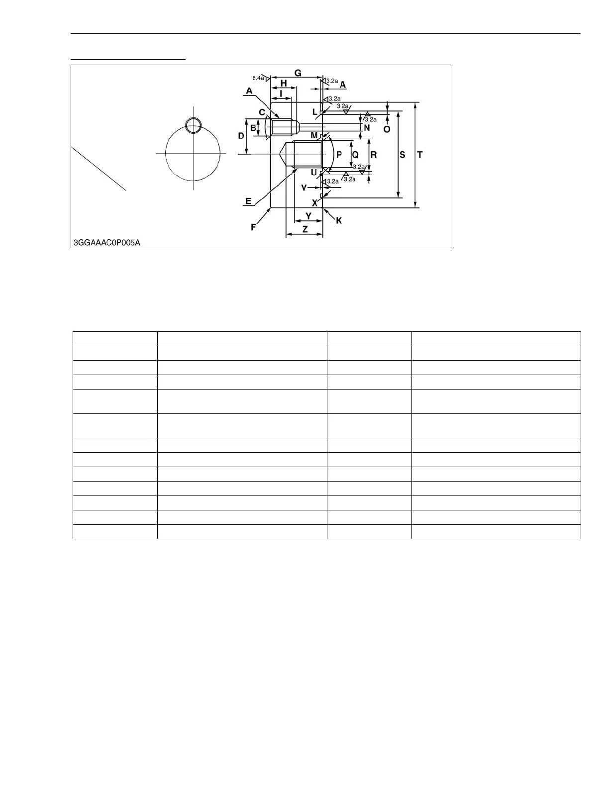
Flange for Control Valve
1. Use for checking the relief valve setting pressure.
NOTE
• When using , attach with following parts.
1. O-ring: 04811-10240
2. O-ring: 04811-10600.
A RP 1/4 N 5 mm dia. (0.20 in. dia.)
B 14.5 mm dia. (0.59 in. dia.) O 2.70 to 2.95 mm (0.106 to 0.116 in.)
C 2.09 rad (120 °) P 2.09 rad (120 °)
D 20 mm (0.79 in.) Q 20 mm dia. (0.79 in. dia.)
E 3/4-16 UNF R 23.95 to 24.00 mm dia.
(0.9429 to 0.9449 in. dia.)
F Chamfer 1mm (0.04 in.) S 63.00 to 63.05 mm dia.
(2.4803 to 2.4823 in. dia.)
G 38 mm (1.50 in.) T 76 mm dia. (2.99 in. dia.)
H 18 mm (0.71 in.) U R 0.5 mm (0.02 in.)
I 15 mm (0.59 in.) V 1.4 to 1.5 mm (0.055 to 0.059 in.)
J 1.4 to 1.5 mm (0.055 to 0.059 in.) W 2.70 to 2.95 mm (0.106 to 0.116 in.)
K Chamfer 1mm (0.04 in.) X R 0.5mm (0.02 in.)
L R 0.5 mm (0.02 in.) Y 20 mm (0.79 in.)
M R 0.5 mm (0.02 in.) Z 26 mm (1.02 in.)

 Loading...