ENGINE
GL6000A-AU-B, GL6000D-AU-B,GL9000A-AU-B, GL9000D-AU-B, WSM
1-S38
(4) Crankshaft
Flywheel
1. Fit the stopper to the flywheel.
2. At first, remove two pieces of the flywheel screws.
3. Insert two pieces of the flywheel guide screws in the holes.
4. Remove all flywheel screws.
5. Remove the flywheel slowly along the flywheel guide screws.
(When reassembling)
• Insert two pieces of the flywheel guide screws.
• Fit the flywheel giving care to the position.
• Apply engine oil to the threads and the undercut surface of the
flywheel screw and fit the screw.
9Y1211607ENS0056US0
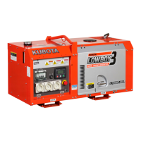
Bearing Case Cover
1. Remove the bearing case cover mounting screws (3), (6). First,
remove inside screws (6) and then outside screws (3).
2. Remove the bearing case cover (5).
• The length of inside screws and outside screws are
different. Do not take a mistake using inside screws and
outside screws.
(When reassembling)
• Fit the bearing case gasket (1) and the bearing case cover
gasket (2) with correct directions.
• Install the bearing case cover to position the casting mark
"UP"on it upward.
• Apply engine oil to the oil seal lip and take care that it is not
rolled when installing.
• Tighten the bearing case cover mounting screws with even
force on the diagonal line.
9Y1211607ENS0057US0
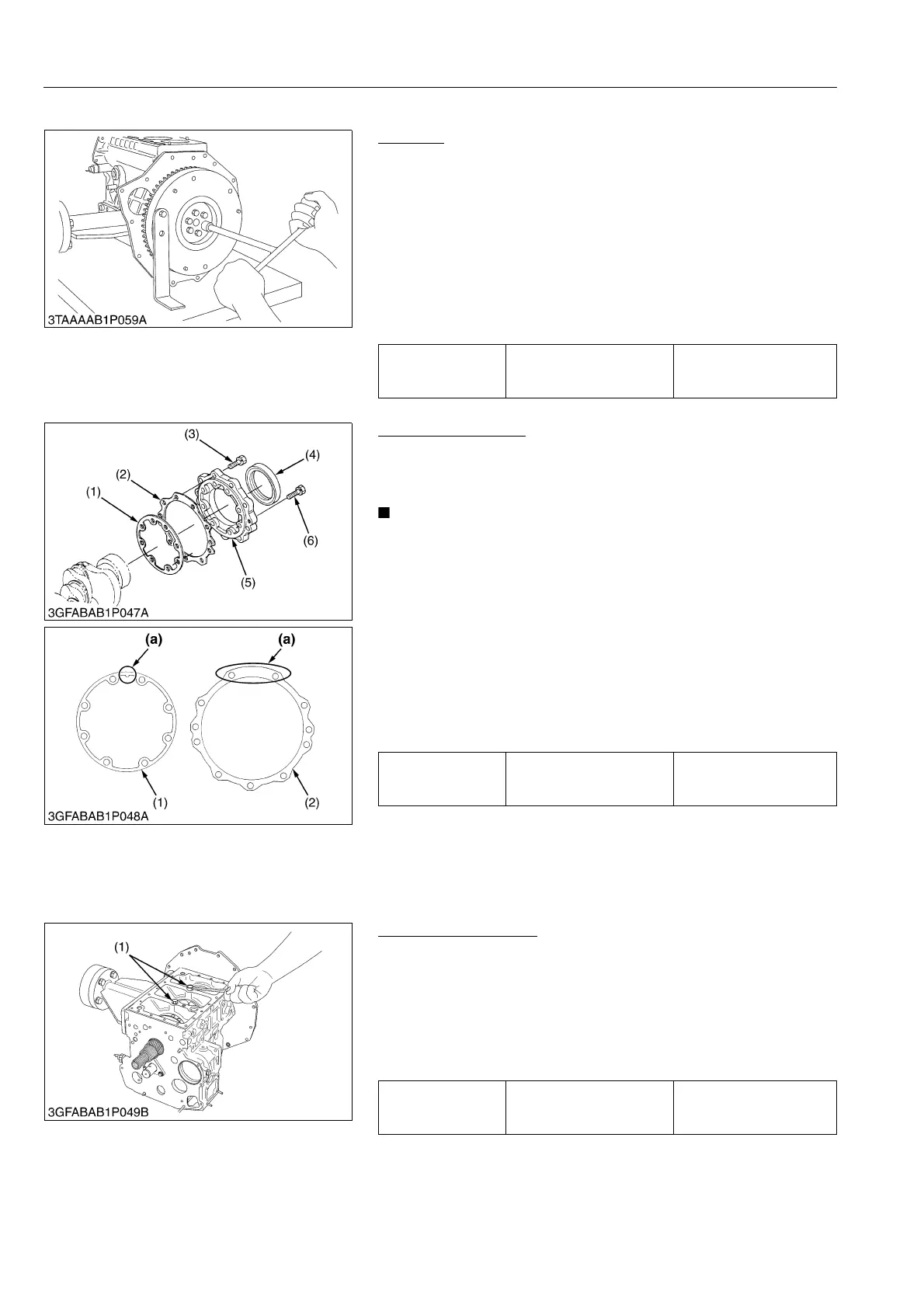
Crankshaft Assembly
1. Remove the main bearing case screw 2 (1).
2. Pull out the crankshaft assembly.
(When reassembling)
• Clean the oil passage of the crankshaft with compressed air.
• Apply oil to the main bearing case screw 2 (1).
• Install the crankshaft assembly, aligning the screw hole of main
bearing case with the screw hole of crankcase.
9Y1211607ENS0058US0
Tightening torque Flywheel screw
54 to 58 N·m
5.5 to 6.0 kgf·m
40 to 43 lbf·ft
Tightening torque
Bearing case cover
mounting screw
9.81 to 11.2 N·m
1.00 to 1.15 kgf·m
7.24 to 8.31 lbf·ft
(1) Bearing Case Gasket
(2) Bearing Case Cover Gasket
(3) Bearing Case Cover Mounting
Screw (Outside M6 × 22)
(4) Oil Seal
(5) Bearing Case Cover
(6) Bearing Case Cover Mounting
Screw (Inside M6 × 20)
(a) Upside
Tightening torque Main bearing case screw 2
27 to 30 N·m
2.7 to 3.1 kgf·m
20 to 22 lbf·ft
(1) Main Bearing Case Screw 2
 Loading...