ENGINE
GL6000A-AU-B, GL6000D-AU-B,GL9000A-AU-B, GL9000D-AU-B, WSM
1-S32
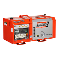
(2) Timing Gears, Camshaft, Fuel Camshaft and Oil Pan
Injection Pump, Fuel Feed Pump and Speed Control Plate
1. Remove the fuel feed pump.
2. Remove the screws (1) and separate the speed control plate
(2), taking care not to damage the governor spring (4) and start
spring (5).
3. Disconnect the governor spring (4) and remove the speed
control plate (2).
(When reassembling)
• Hook the governor spring (4) to the lever (6) first and install the
speed control plate (2).
• Be sure to place the copper washers underneath two screws
(1).
• Position the slot (10) on the fork lever just under the slot (9) on
the crankcase.
• Insert the injection pump (3) so that the control rod (8) should be
pushed by the high idle spring (7) at its end and the pin (11) on
the rod engages with the slot (10) on the fork lever.
• The sealant is applied to both sides of the soft metal gasket
shim. The liquid gasket is not required for assembling.
• Addition or reduction of shim (0.025 mm, 0.00098 in.)
delays or advances the injection timing by approx.
0.009 rad (0.5°).
• In disassembling and replacing, be sure to use the same
number of new gasket shims with the same thickness.
9Y1211607ENS0045US0
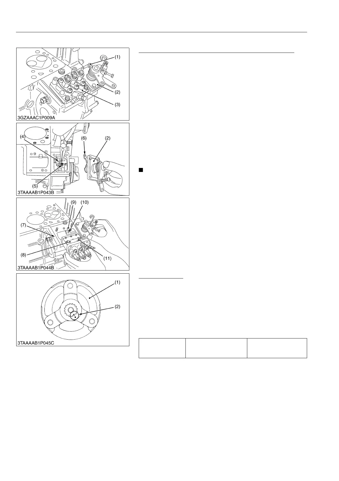
Fan Drive Pulley
1. Set the stopper to the flywheel.
2. Remove the fan drive pulley screw.
3. Draw out the fan drive pulley (1) with a puller.
(When reassembling)
• Install the pulley to the crankshaft, aligning the alignment mark
(2) on them.
• Apply engine oil to the fan drive pulley retaining screws. And
tighten them.
9Y1211607ENS0046US0
(1) Screw
(2) Speed Control Plate
(3) Injection Pump
(4) Governor Spring
(5) Start Spring
(6) Lever
(7) High Idle Spring
(8) Control Rod
(9) Slot (Crankcase Side)
(10) Slot (Fork Lever Side)
(11) Pin
Tightening torque Fan drive pulley screw
98.1 to 107 N·m
10.0 to 11.0 kgf·m
72.4 to 79.5 lbf·ft
(1) Fan Drive Pulley (2) Alignment Mark
 Loading...