ENGINE
GL6000A-AU-B, GL6000D-AU-B,GL9000A-AU-B, GL9000D-AU-B, WSM
1-M4
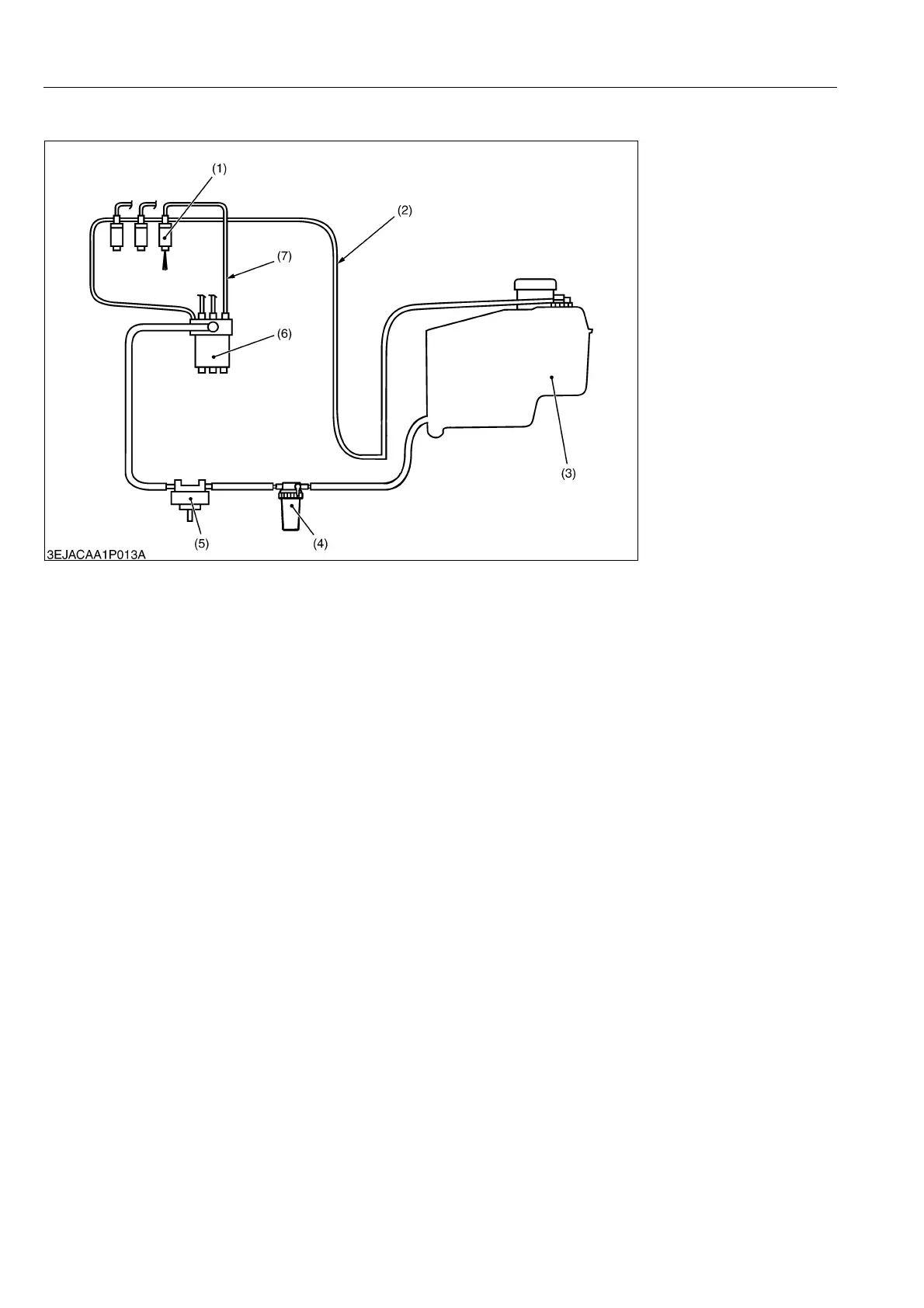
4. FUEL SYSTEM
Fuel from the fuel tank (3) passes through the fuel filter (4), and then enters the injection pump (6) after impurities
such as dirt, water, etc. are removed.
The fuel pressurized by the injection pump to the opening pressure (13.73 to 14.71 MPa, 140 to 150 kgf/cm
2
, 1990
to 2133 psi), of the injection nozzle (1) is injected into the combustion chamber.
Part of the fuel fed to the injection nozzle (1) lubricates the moving parts of the needle valve inside the nozzle,
then returns to the fuel tank through the fuel overflow pipe (2) from the upper part of the nozzle holder.
9Y1211607ENM0004US0
(1) Injection Nozzle
(2) Fuel Overflow Pipe
(3) Fuel Tank
(4) Fuel Filter
(5) Mechanical Fuel Feed Pump
(6) Injection Pump
(7) Injection Pipe
 Loading...