ENGINE
GL6000A-AU-B, GL6000D-AU-B,GL9000A-AU-B, GL9000D-AU-B, WSM
1-S58
(6) Oil Pump
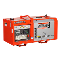
Rotor Lobe Clearance
1. Measure the clearance between lobes of the inner rotor and the
outer rotor with a thickness gauge.
2. If the clearance exceeds the factory specification, replace the oil
pump rotor assembly.
9Y1211607ENS0099US0
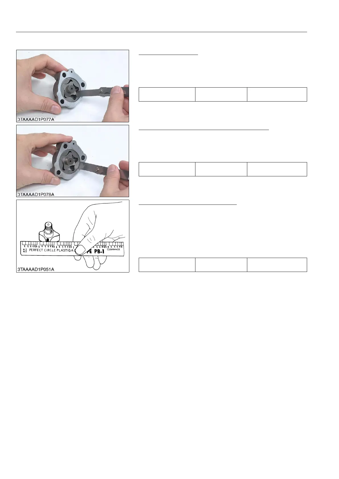
Clearance between Outer Rotor and Pump Body
1. Measure the clearance between the outer rotor and the pump
body with a thickness gauge.
2. If the clearance exceeds the factory specification, replace the oil
pump rotor assembly.
9Y1211607ENS0100US0
Clearance between Rotor and Cover
1. Put a strip of plastigauge (Code No. 07909-30241) onto the
rotor face with grease.
2. Install the cover and tighten the screws.
3. Remove the cover carefully, and measure the amount of the
flattening with the scale and get the clearance.
4. If the clearance exceeds the factory specification, replace oil
pump rotor assembly.
9Y1211607ENS0101US0
Rotor lobe clearance Factory specification
0.030 to 0.14 mm
0.0012 to 0.0055 in.
Clearance between outer
rotor and pump body
Factory specification
0.070 to 0.15 mm
0.0028 to 0.0059 in.
Clearance between rotor
and cover
Factory specification
0.0750 to 0.135 mm
0.00296 to 0.00531 in.
 Loading...