CDI UNIT
INSPECTION
Disconnect the CDI unit coupler.
Check for continuity with the coupler on
the hardness wire side and CDI unit.
Inspection table is as follows.
The CDI unit is fully transistorized. For
accurate testing, it is necessary to use a
specified tester. Use of an improper
tester or measurements in an improper
range may give false readings.
*
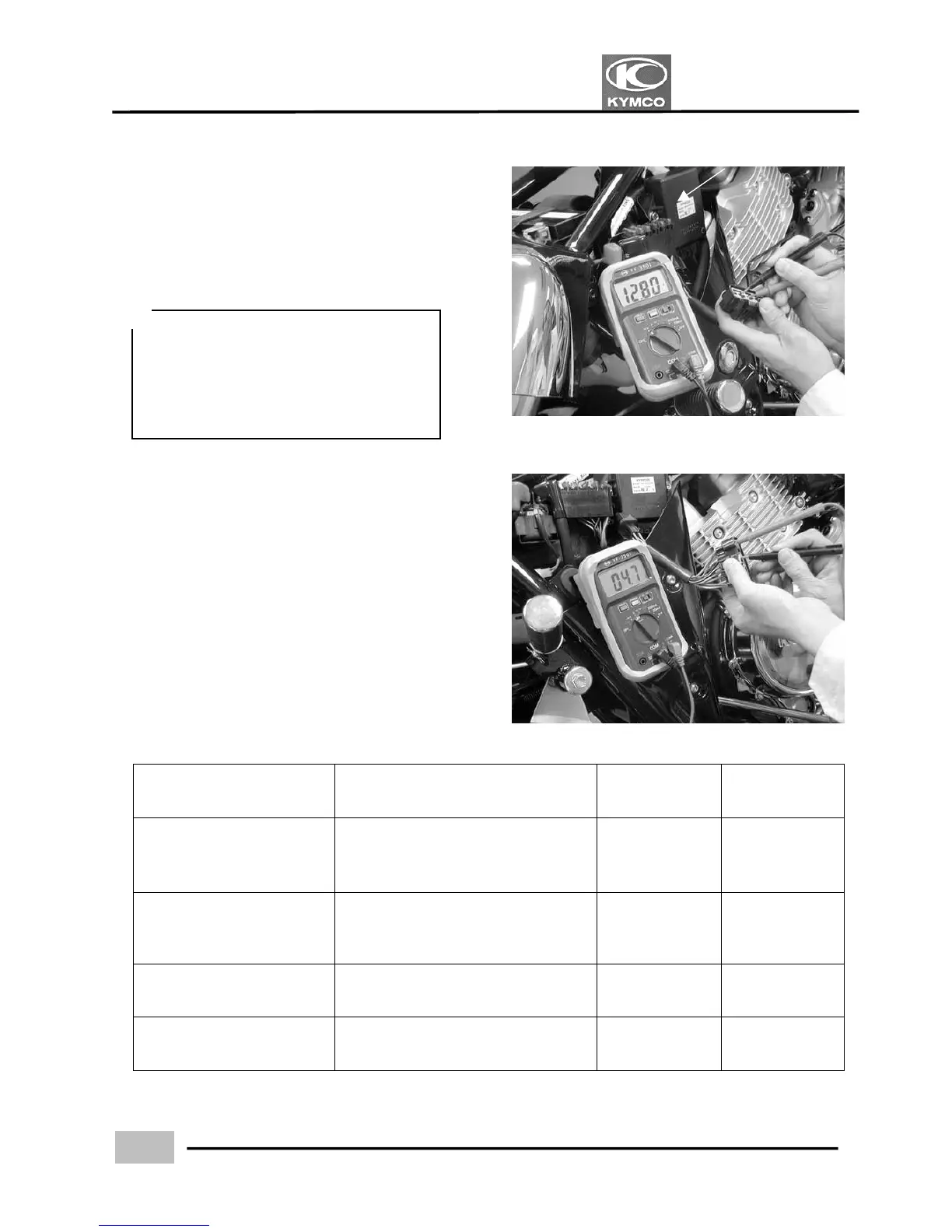
Picture A
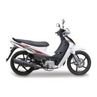
Picture B
Item Terminal Standard Remark
Continuity from ignition
switch to CDI unit
Black/white and green
(ignition switch “ON”, engine stop
switch “RUN”)
Battery voltage Picture A
Primary coil
Black/white and green/orange
Black/white and green/gray
3.57:~4.83: Picture B
Pulser coil Green/white and blue/yellow 396阡594: Picture C
Continuity for CDI unit Green/white and green Continuity Picture D