6. CYLINDER HEAD/VALVES
6-3
VENOX250/250i
SERVICE INFORMATION
GENERAL INSTRUCTIONS
x When assembling, apply engine oil to the valve guide movable parts, valve arm and camshaft
sliding surfaces for initial lubrication.
x The valve rocker arm is lubricated with engine oil through the cylinder head engine oil passages.
Clean and unclog the oil passages before cylinder head assembly.
x After disassembly, clean the removed parts and dry them with compressed air before inspection.
x After removal, mark and arrange the removed parts in order. When assembling, install them in
the reverse order of removal.
x The cylinder head and holder need to be replaced if anyone broken.
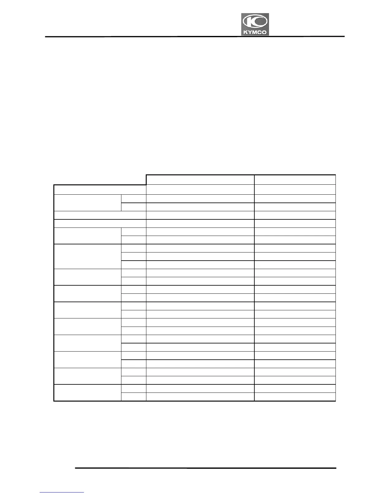
SPECIFICATIONS
Standard (mm) Service Limit (mm)
Item VENOX250 VENOX250
IN 0.1mm —
Valve clearance (cold)
EX 0.1mm —
Compression pressure (kg/cm²) 17±2 —
Cylinder head warpage — 0.1
IN 34.40 —
Camshaft cam height
EX 34.40 —
R 23.978~23.990 23.90
C 23.90~23.920 23.80
Camshaft height
L 23.978~23.990 23.90
IN 10.0~10.015 10.040
Rocker arm I.D.
EX 10.0~10.015 10.040
IN 9.975~9.990 9.94
Rocker arm shaft O.D.
EX 9.975~9.990 9.94
IN 0.04 —
Rocker arm-to-shaft
clearance
EX 0.04 —
IN 90º+1.0 —
Valve seat angle
EX 90º+1.0 —
IN 4.975~4.990 4.90
Valve stem O.D.
EX 4.975~4.990 4.90
IN 4.95~5.0 5.05
Valve guide I.D.
EX 4.95~5.0 5.05
IN Inner:29.8 Outer:33.6 Inner:29.8 Outer:33.6
Valve spring free
length
EX Inner:29.8 Outer:33.6 Inner:29.8 Outer:33.6
IN 0.175 —
Valve stem-to-guide
clearance
EX 0.155 —
 Loading...