18. LIGHTS/INSTRUMENT/SWITCHES/HORN
VENOX250/250i
18-4
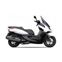
INSPECTION
Check for continuity between the wires
indicated below.
Color
Position
Black Red/White
OFF
ON ○ ○
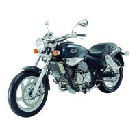
STARTER BUTTON
Disconnect the right switch wire coupler.
Check for continuity between the
black/white and yellow/red wires.
Color
Position
Black/White Yellow/Red
FREE
PUSH ○ ○
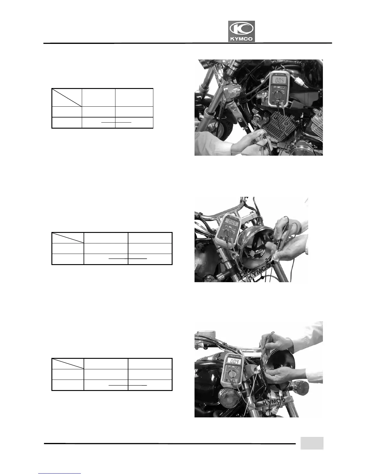
HORN BUTTON
Disconnect the left switch wire coupler.
Check for continuity between the
brown/blue and light green wires.
Color
Position
Brown/Blue Light Green
FREE
PUSH ○ ○
S
 Loading...