COMPONENT MAINTENANCE MANUAL
AVIATION RECORDERS
Model FA5000
Initial Issue Page 310
Sep. 30/11
Disassembly
23–70–40
Use or disclosure of information on this sheet is subject to
the restrictions on the cover page of this document.
(1−30)
(1−35)
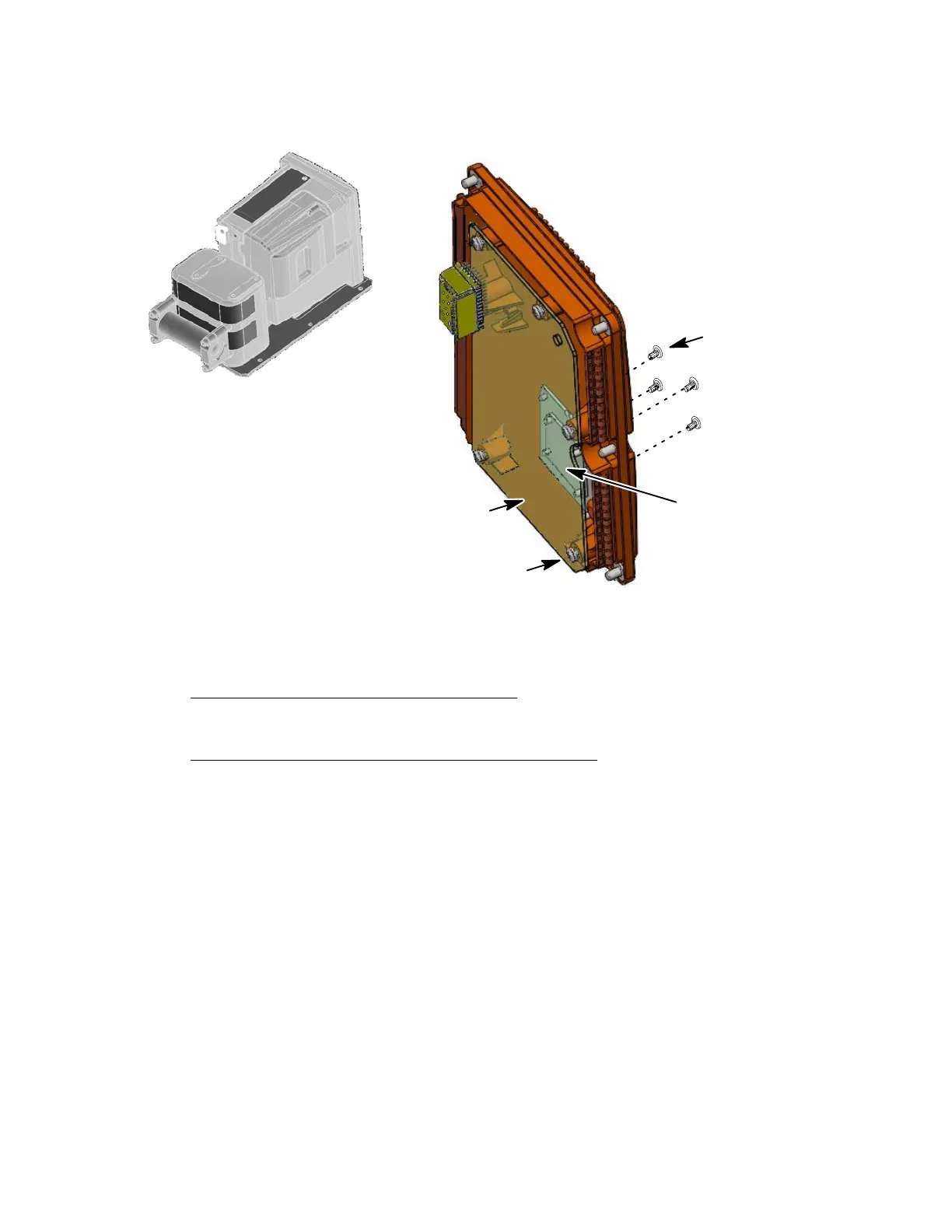
(Qty. 6)
(Qty. 4)
(1−40)
Rear Connector
J−1
Some parts are removed
for clarity purposes
NOTE:
Figure 305.
Aircraft Interface (AI) PWA Removal Diagram
E. Main Processor (MP) PWA Removal
(See Figure 306 or IPL Figure 1, Item 50)
MAIN PROCESSOR PWA REMOVAL PROCEDURE
(1) Remove the rear cover (1−10) as described in Paragraph C, Rear Cover Re-
moval.
(2) Disconnect the hold−up capacitor cables at J−6 and J−7 and on the MP PWA
(1−50).
(3) Disconnect the RIPS cable (1−85) at P−5 on the MP PWA (1−50).
(4) Remove the two screws (1−115) used to secure the CSMU cable cover plate
(1-110) and remove cover plate.
(5) Remove the two screws (1−135) used to secure CSMU cable (1−120) connect-
or to the MP PWA (1−50) and remove CSMU cable connector.
(6) Remove the one cover (1−60), screw (1−65), spacer (1−70) and two springs
(1−75) used to secure the top half Ethernet connector J−2 to the front part of
the Shielded Housing (1−5).
The document reference is online, please check the correspondence between the online documentation and the printed version.
 Loading...