COMPONENT MAINTENANCE MANUAL
AVIATION RECORDERS
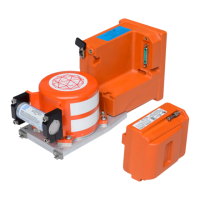
Model FA5000
Initital Issue Page 15
Sep. 30/11
Description and Operation
23–70−40
Use or disclosure of information on this sheet is subject to
the restrictions on the cover page of this document.
B2, C2,
D3, E3,
G10,
G11,
H10,
H11
Signal Ground
C11,
D11
Chassis Ground
AI PWA Connector: HM-H088FL1-8CS1-TG30
Processor PWA Connector: HM-S088FL1-8AP1-TG30
Hold Up Capacitor Voltage to Aircraft Interface PWA, J2
Table 3. Hold Up Capacitor Voltage to CPU PWA, J6
CONN
PIN
SIGNAL NAME AI
PWA
I/O
1, 2 HoldUPCap_Voltage Out
+40 volts DC output to recorder hold up
capacitor.
Connector: Amphenol 62650-1
Mate:
Table 4. Hold Up Capacitor Voltage Return to CPU PWA, J7
CONN
PIN
SIGNAL NAME AI
PWA
I/O
1, 2 40VDC_RTN In
+40 volts DC return from hold up capacit
or.
Connector: Amphenol 62650-1
Mate:
Table 5. Aircraft Interface PWA to Video Board PWA, J4
VIDEO
PIN
SIGNAL NAME AI
PWA
I/O
Outer VIDEO_OUT_LO Out Standard ground. Compliant to PAL B.
Inner VIDEO_OUT_HI Out
Single ended video input signal. Compli
ant to PAL B. 75 Ohm impedance to
standard ground.
The document reference is online, please check the correspondence between the online documentation and the printed version.
 Loading...